Combined vertical hanging and dry hanging system

A combination type, vertical hanging technology, applied in the direction of covering/lining, construction, building structure, etc., can solve the problems of difficult adjustment of flatness, waste of materials, non-environmental protection, etc., to achieve convenient and fast installation and disassembly Environmentally friendly and use reduction effects

Pending Publication Date: 2022-06-24
佛山市速居家居科技有限公司
View PDF6 Cites 0 Cited by
  • Summary
  • Abstract
  • Description
  • Claims
  • Application Information

AI Technical Summary

Problems solved by technology

[0003] At present, in the installation process of finished rock slabs, due to the large size of rock slabs, high installation requirements, difficult adjustment of flatness, more material waste, and the use of gun nails and glue in the construction process, the traditional finished rock slabs Installation has disadvantages such as time-consuming, waste of materials, difficult to disassemble and modify, and not environmentally friendly.

Method used


Image

  • Combined vertical hanging and dry hanging system
  • Combined vertical hanging and dry hanging system
  • Combined vertical hanging and dry hanging system

Examples


Embodiment 1

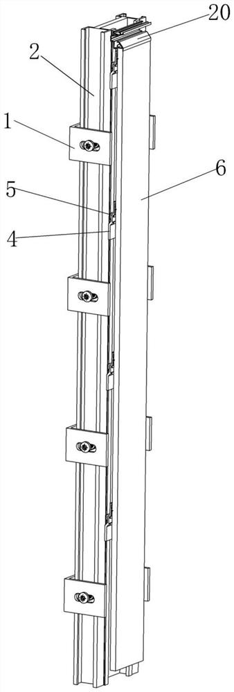
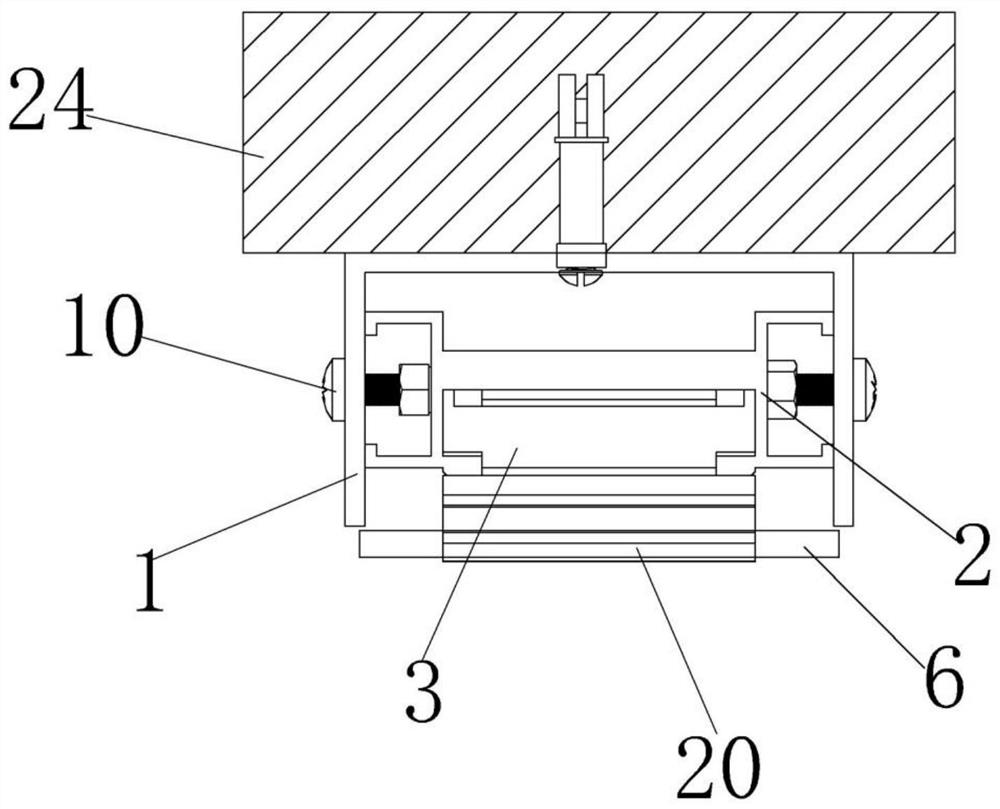
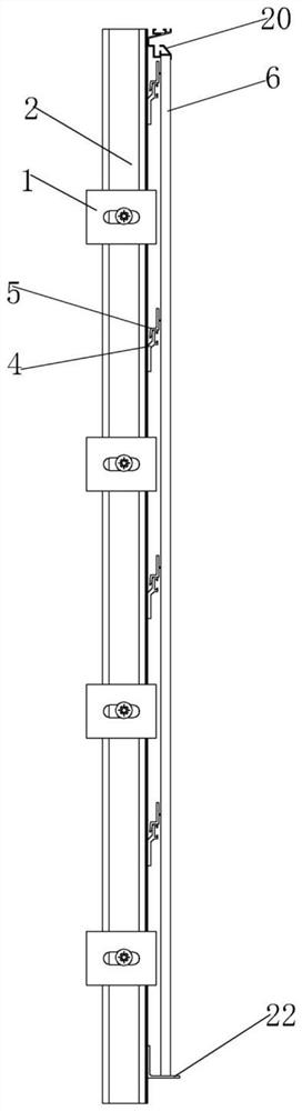
[0037] Embodiment 1: A combined vertical hanging dry hanging system provided in this embodiment is mainly composed of a U-shaped base 1, a vertical keel 2, a horizontal keel 4 and a hanging piece 5. The U-shaped base 1 is exploded Screws are fixed on the wall 24, the U-shaped base 1 is installed with a vertical keel 2, a connection base 3 is installed in the vertical keel 2, and a horizontal keel 4 is installed on one side of the connection base 3, so The connecting base 3 and the horizontal keel 4 are fixedly and clamped on the vertical keel 2 by screws, and a hanging piece 5 is installed on the horizontal keel 4, and a rock plate 6 is installed on the hanging piece 5, and the rock plate 6 passes through. The hanging piece 5 is installed on the horizontal keel 4 .

[0038] The U-shaped base 1 includes a mounting portion 7 and a bending portion 8 disposed at both ends of the mounting portion 7 . Both the mounting portion 7 and the bending portion 8 are provided with mounting h...

Embodiment 2

[0040] Embodiment 2: This embodiment further makes the following installation scheme as an improvement on the basis of the above-mentioned Embodiment 1. First, the U-shaped base 1 is installed on both sides of the vertical keel 2 by adjusting screws 10, and then the U-shaped base 1 is installed on the vertical keel 2. Install the explosion screw on the top, and the explosion screw passes through the vertical keel 2 and the U-shaped base 1 in turn, so as to install the U-shaped base 1 and the vertical keel 1 on the wall 24, and then install the connection base 3 in the vertical keel 2 in turn. , the horizontal keel 4 and the hanging piece 5, this installation method is different from the first embodiment, the U-shaped base 1 and the vertical keel 2 are first installed on each other, and then installed on the wall 24 through the explosion screw, and this installation is adopted. In this way, the quick installation of the U-shaped base 1 and the vertical keel 2 is realized, and th...

Embodiment 3

[0041] Embodiment 3: One end of the vertical keel 2 is installed with a trim strip 20, the edge trim 20 is mounted on the vertical keel 2 by screws, and is installed at the opening of the snap groove 11, and the edge trim 20 is provided with Matching groove 21, the rock plate 6 is installed in the matching groove 21, and the hanging piece 5 includes a hanging end 18 and a connecting end 19. The hanging end 18 is arranged below the connecting end 19. During installation, the hanging piece 5 is on the The hanging end 18 of the hanging piece is installed on the hanging end 16 of the horizontal keel 4, and the connecting end 19 of the hanging piece 5 is installed with the rock plate 6.

[0042] The rock plate 6 is installed on the hanging piece 5 in advance by means of plugging and other methods to form a whole, and then the hanging piece 5 is installed on the horizontal keel 4. At this time, one end of the hanging piece 5 is inserted into the matching groove 21 of the edge strip 2...


PUM


Abstract

The invention discloses a combined vertical hanging and dry hanging system which comprises a U-shaped base, the U-shaped base is fixed to a wall through explosive screws, a vertical keel is installed on the U-shaped base, a connecting base is installed in the vertical keel, a transverse keel is installed on one side of the connecting base, and the connecting base and the transverse keel are fixedly clamped to the vertical keel through screws. The hanging pieces are installed on the transverse keels, the rock plates are installed on the hanging pieces, the rock plates are installed on the transverse keels through the hanging pieces, the U-shaped base is arranged, the vertical keels are installed on the U-shaped base, then the transverse keels are installed on the vertical keels, the hanging pieces are installed on the transverse keels, and the rock plates are installed on the hanging pieces. The novel rock plate is simple in structure, easy to process, low in cost, capable of solving the problems that the rock plate is not environmentally friendly, free of glue and bottoming, uneven in wall surface, difficult to install and the like, firm and easy to assemble and disassemble, and the use of fasteners is reduced, so that the rock plate is more convenient and quicker to assemble and disassemble.

Description

technical field [0001] The invention relates to the technical field of decoration, in particular to a combined vertical hanging dry hanging system. Background technique [0002] In prefabricated decoration, pendants (including various keels and profiles) are often used to fix targets such as rock slabs, ceramic tiles, and glass curtain walls. Due to the large size error of the building, the ease of assembly and size adjustability during the assembly process are particularly important. [0003] At present, in the process of installing the finished slate, due to the large volume of the slate, the high installation requirements, the difficulty in adjusting the flatness, the waste of materials, and the inevitable use of gun nails and glue during the construction process, the traditional finished slate Installation has disadvantages such as time-consuming, waste of materials, difficulty in dismantling and modification, and environmental protection. SUMMARY OF THE INVENTION ...

Claims


Application Information

Patent Timeline
Patent Type & Authority Applications(China)
IPC IPC(8): E04F13/21E04F13/22
CPCE04F13/0803E04F13/0805
Inventor 李强
Owner 佛山市速居家居科技有限公司
Why Eureka
Try Eureka