
Two-stage rotor compressor

A rotor compressor and male rotor technology, applied in the field of compressors, can solve the problems of large refrigerant leakage, poor shaft seal tightness, and high exhaust temperature, and achieve the effects of improving leakage problems, shortening size, and shortening spacing distances.

Pending Publication Date: 2022-06-24
FUSHENG IND SHANGHAI
View PDF0 Cites 0 Cited by
  • Summary
  • Abstract
  • Description
  • Claims
  • Application Information

AI Technical Summary

Problems solved by technology

[0002] The two-stage rotor of the existing two-stage rotor compressor is connected to the low-pressure side. Under low temperature conditions, when the evaporation temperature is too low, the atmospheric pressure may be higher than the low pressure. In the system, the exhaust temperature is too high, or the moisture in the air enters the refrigeration system and causes icing
When the two-stage rotor is connected to the high-pressure side, although air can be prevented from entering the refrigeration system, since the high-pressure pressure is greater than the external pressure, it may cause a large amount of refrigerant leakage

Method used


Image

  • Two-stage rotor compressor
  • Two-stage rotor compressor
  • Two-stage rotor compressor

Examples


Embodiment Construction

[0075] Exemplary embodiments embodying the features and advantages of the present invention will be described in detail in the following description. It should be understood that the present invention can have various changes in different embodiments without departing from the scope of the present invention, and the descriptions and accompanying drawings are essentially for illustration purposes, rather than for limiting the present invention. invention.

[0076] In the following description of various exemplary embodiments of the present invention, reference is made to the accompanying drawings, which form a part hereof, and in which are shown by way of example various exemplary structures, systems in which aspects of the present invention may be implemented and steps. It is to be understood that other specific arrangements of components, structures, exemplary devices, systems and steps may be utilized and structural and functional modifications may be made without departing...


PUM


Abstract

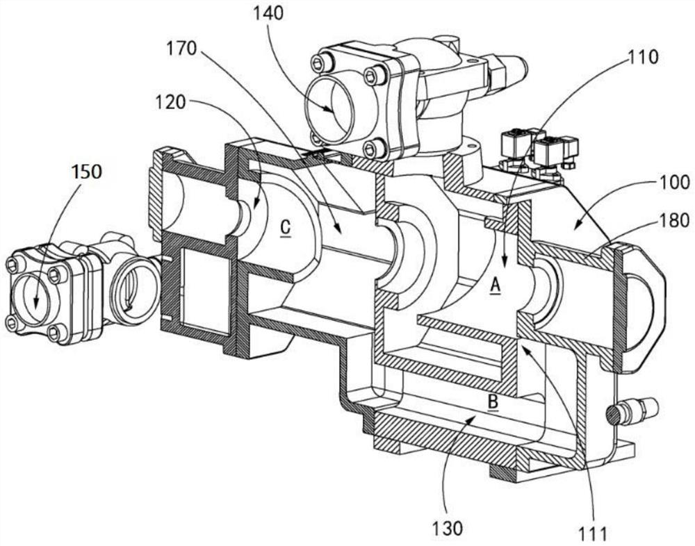
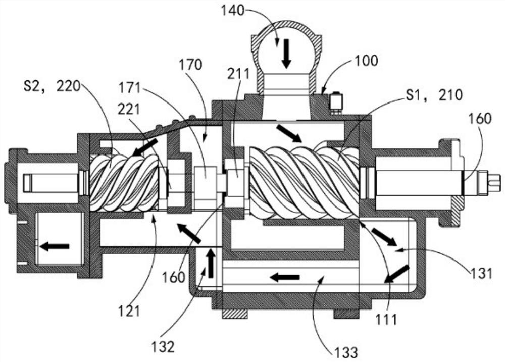
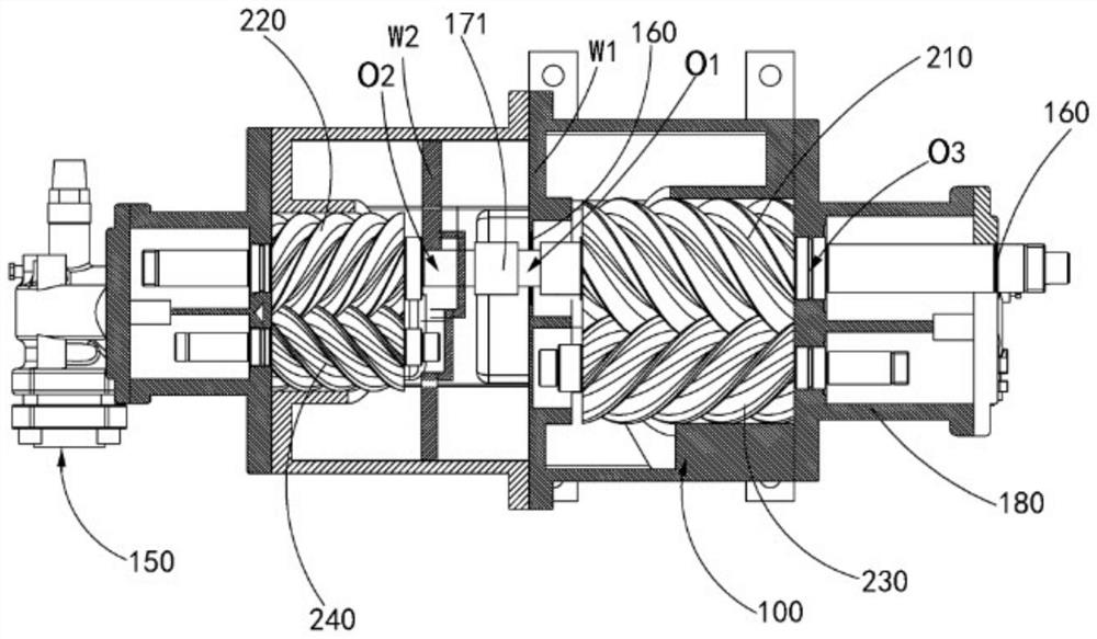
The invention provides a two-stage rotor compressor. The two-stage rotor compressor comprises a machine shell, a first pressurizing chamber, a second pressurizing chamber, a first rotor set, a second rotor set, a middle pressure flow channel, an air suction port and an air exhaust port. The first pressurizing chamber and the second pressurizing chamber are arranged in the machine shell. The first rotor set and the second rotor set are arranged in the first pressurizing chamber and the second pressurizing chamber respectively, and the first male rotor and the second male rotor are coaxially connected; the middle pressure flow channel is communicated between the high-pressure side of the first pressurizing chamber and the low-pressure side of the second pressurizing chamber; the air suction port and the exhaust port are formed in the machine shell, the air suction port communicates with the low-pressure side of the first pressurizing chamber, and the exhaust port communicates with the high-pressure side of the second pressurizing chamber; the pressurizing direction of the first pressurizing chamber in the axial direction of the first rotor set is opposite to the pressurizing direction of the second pressurizing chamber in the axial direction.

Description

technical field [0001] The invention relates to the technical field of compressors, in particular to a two-stage rotor compressor. Background technique [0002] The two-stage rotor of the existing two-stage rotor compressor is connected to the low-pressure side. Under low temperature conditions, when the evaporation temperature is too low, the atmospheric pressure may be higher than the low-pressure pressure. If the shaft seal is poorly sealed, air will enter the refrigeration system. In the system, the exhaust temperature is too high, or the moisture in the air enters the refrigeration system and causes freezing. When the two-stage rotor is connected to the high-pressure side, although the air can be prevented from entering the refrigeration system, the high-pressure pressure is greater than the external pressure, which may lead to a large amount of refrigerant leakage. SUMMARY OF THE INVENTION [0003] A main purpose of the present invention is to overcome at least one ...

Claims


Application Information

Patent Timeline
Patent Type & Authority Applications(China)
IPC IPC(8): F04C23/00F04C18/16F04C29/00F04C29/12
CPCF04C23/001F04C18/16F04C29/00F04C29/12F04C29/128
Inventor 李侑庭邹培培张伟平
Owner FUSHENG IND SHANGHAI
Learn More