Camera and laser radar synchronous control system and method and storage medium

A laser radar and synchronous control technology, applied in the direction of radio wave measurement systems, instruments, measuring devices, etc., can solve the problem that the laser radar and the camera cannot be synchronized accurately, and achieve the effect of accurate and convenient data, easy processing, and synchronization accuracy

Pending Publication Date: 2022-06-24
深兰人工智能(深圳)有限公司
View PDF0 Cites 0 Cited by
  • Summary
  • Abstract
  • Description
  • Claims
  • Application Information

AI Technical Summary

Problems solved by technology

When there are multiple lidars and cameras, it will cause inaccurate synchronization between the lidar and the camera

Method used


Image

  • Camera and laser radar synchronous control system and method and storage medium
  • Camera and laser radar synchronous control system and method and storage medium
  • Camera and laser radar synchronous control system and method and storage medium

Examples


Embodiment 1

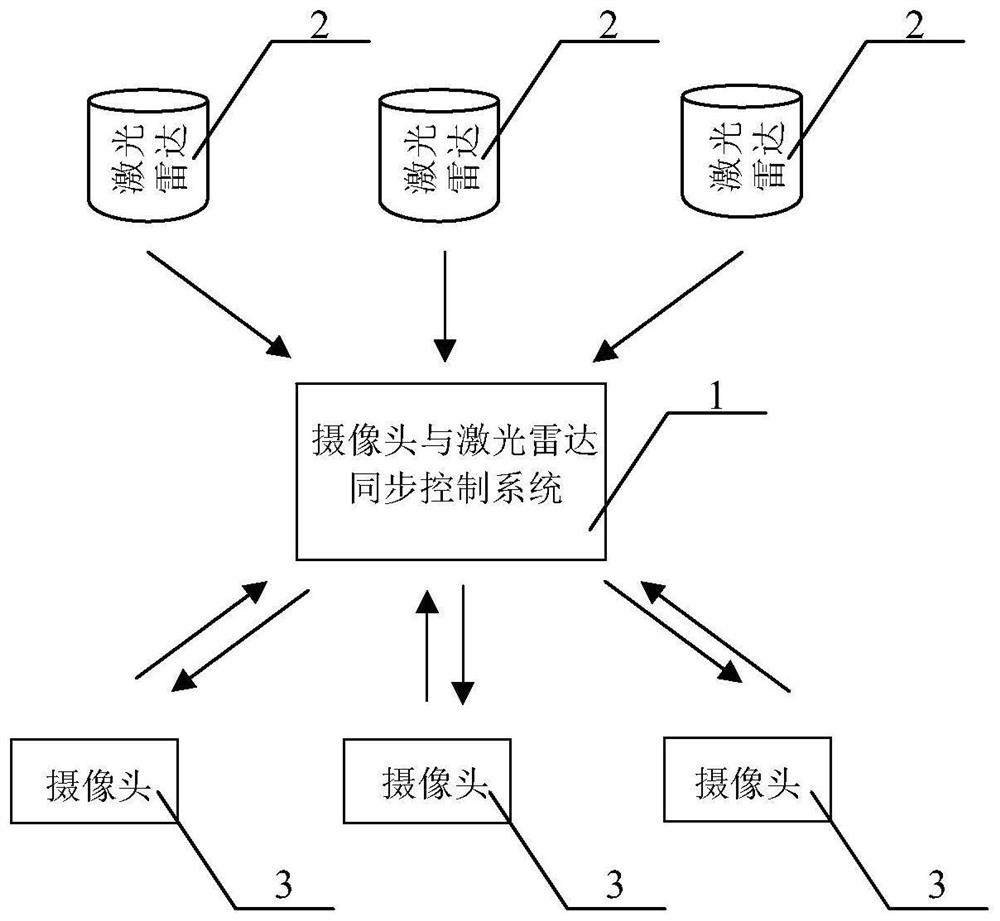
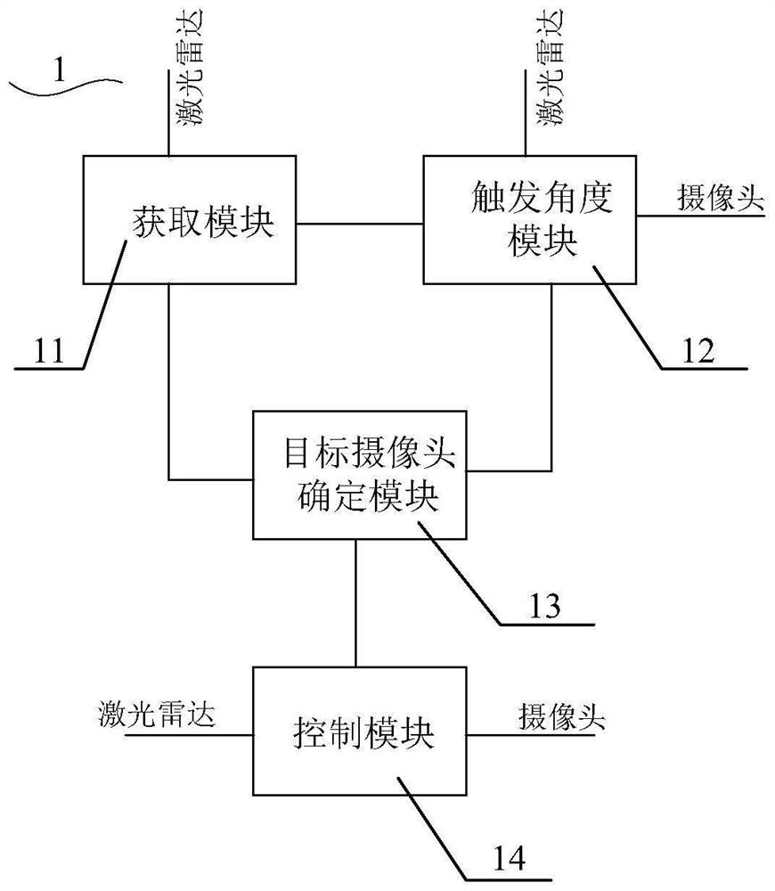
[0048] see figure 1 and figure 2 As shown, in the present embodiment, a camera and lidar synchronization control system 1 is provided, the camera and lidar synchronization control system 1 is connected with the lidar 2 and the camera 3, and the camera and lidar synchronization control system 1 includes:

[0049] The acquisition module 11, which is connected with the laser radar 2, is used to obtain the scanning angle and the timestamp of the scanning angle in the real-time scanning process of the laser radar 2; the triggering angle module 12, the triggering angle module 12 is connected to the acquisition module 11, the lidar 2 and each camera 3, and is used for according to the time stamp, the attribute information of the lidar 2, the scanning angle, the attribute information of each camera 3 and the The joint calibration information of the lidar 2 and each camera 3 is used to determine the trigger angle and trigger timing of each camera 3; the target camera determination mo...

Embodiment 2

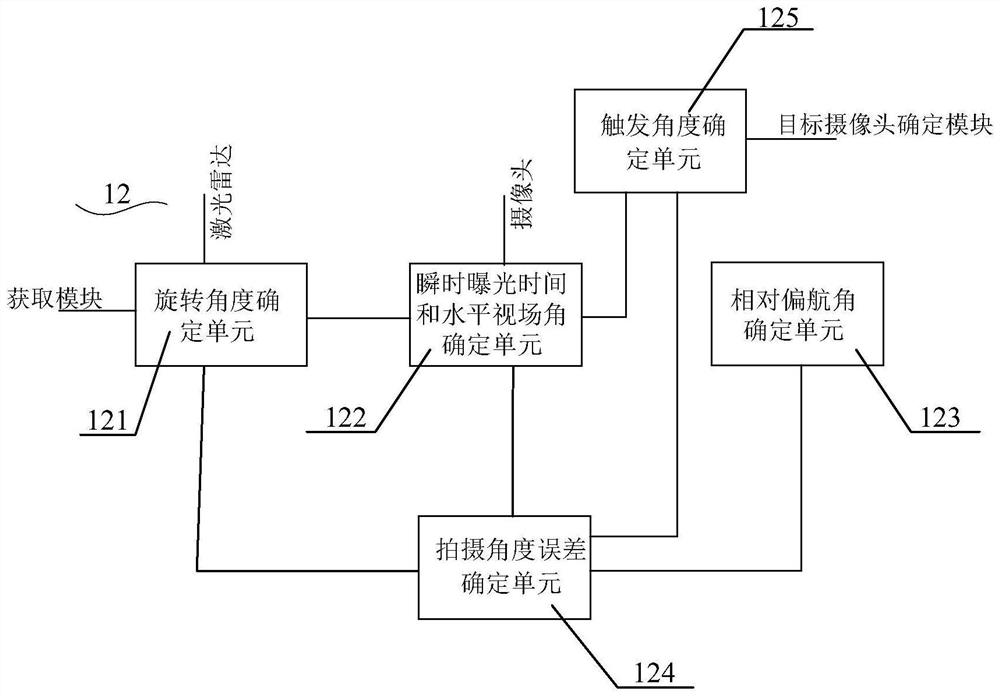
[0053] please continue figure 1 and figure 2 In this embodiment, a camera and lidar synchronous control system 1 is also provided. The camera and lidar synchronous control system 1 includes: an acquisition module 11, a trigger angle module 12, a target camera determination module 13, and a control module 14 , and its connection relationship and function are the same as those in the first embodiment, and will not be repeated here. The main difference between the system proposed in this embodiment and the system in Embodiment 1 is that the trigger angle module 12 further includes several subunits. For details, please refer to the following introduction.

[0054] In this embodiment, a plurality of lidars 2 and a plurality of cameras 3 are used as examples for introduction. Among them, the working states of the plurality of lidars 2 need to be in a synchronized state.

[0055] Specifically, the specific number of the lidar 2 can be set according to actual needs, figure 1 Onl...

Embodiment 3

[0076] please combine Figure 1 to Figure 6 see Figure 7 , this embodiment also provides a camera and lidar synchronization control method, the camera and lidar synchronization control method can be implemented based on the camera and lidar synchronization control system as in Embodiment 1 or Embodiment 2, including:

[0077] S10: Acquire the scanning angle and the timestamp of the scanning angle in the real-time scanning process of the lidar, and obtain the lidar point cloud data when the lidar scans to the scanning angle;

[0078] S20: Determine the trigger angle of each camera according to the timestamp, the attribute information of the lidar, the attribute information of each camera, and the joint calibration information of the lidar and each camera;

[0079] S30: Determine a target camera synchronized with the lidar according to the scanning angle and the triggering angle of each camera;

[0080] S40: When the lidar scans to the trigger angle, the target camera starts ...


PUM


Abstract

The invention provides a camera and laser radar synchronous control system and method and a storage medium. The camera and laser radar synchronous control method comprises the following steps: acquiring a scanning angle and a timestamp of the scanning angle in a real-time scanning process of a laser radar, and acquiring laser radar point cloud data when the laser radar scans to the scanning angle; according to the timestamp, the attribute information of the laser radar, the attribute information of each camera and the joint calibration information of the laser radar and each camera, determining the trigger angle of each camera; determining a target camera synchronized with the laser radar according to the scanning angle and the triggering angle of each camera; and when the laser radar scans to the trigger angle, the target camera starts to execute an operation of acquiring image data, so that the target camera synchronously acquires the image data within a horizontal field angle of the target camera scanned by the laser radar. According to the invention, synchronization of the laser radar point cloud data acquired by the laser radar and the image data acquired by each camera can be ensured.

Description

technical field [0001] The present invention relates to the technical field of automatic driving, in particular to a synchronous control system, method and storage medium of a camera and a laser radar. Background technique [0002] Under the existing vehicle conditions, each camera and lidar act respectively and transfer the data to the processor. Because the lidars do not work synchronously at the same level and in the same phase, although the clocks of the camera and lidar are synchronized, the lidar and each camera do not have an angular coordination action, which will also cause the data obtained by the lidar to be different from the data obtained by the camera. Synchronization, the processor cannot effectively process the camera and lidar point cloud data analysis and fusion. [0003] Under the existing vehicle conditions, the corresponding solution is to jointly calibrate a single lidar and a single camera, obtain the rotation matrix and translation vector between the...

Claims


Application Information

Patent Timeline
Patent Type & Authority Applications(China)
IPC IPC(8): G01S17/86G01S17/931
CPCG01S17/86G01S17/931
Inventor 陈海波李辉余航刘风驰王红辉
Owner 深兰人工智能(深圳)有限公司
Why Eureka
Try Eureka