Supercharge Your Innovation With Domain-Expert AI Agents!

Self-repairing sliding bearing

A sliding bearing and self-repairing technology, which is applied to sliding contact bearings, rotating bearings, bearings, etc., can solve problems such as sliding friction, bearing wear, and failure.

Pending Publication Date: 2022-06-24
ZF FRIEDRICHSHAFEN AG
View PDF0 Cites 0 Cited by
  • Summary
  • Abstract
  • Description
  • Claims
  • Application Information

AI Technical Summary

Problems solved by technology

However, in many applications, such as in wind power transmissions, it is not possible to operate with only sliding friction
If boundary or mixed friction is present, the bearing will wear out and eventually fail at a later stage of wear

Method used


Image

  • Self-repairing sliding bearing

Examples


Embodiment Construction

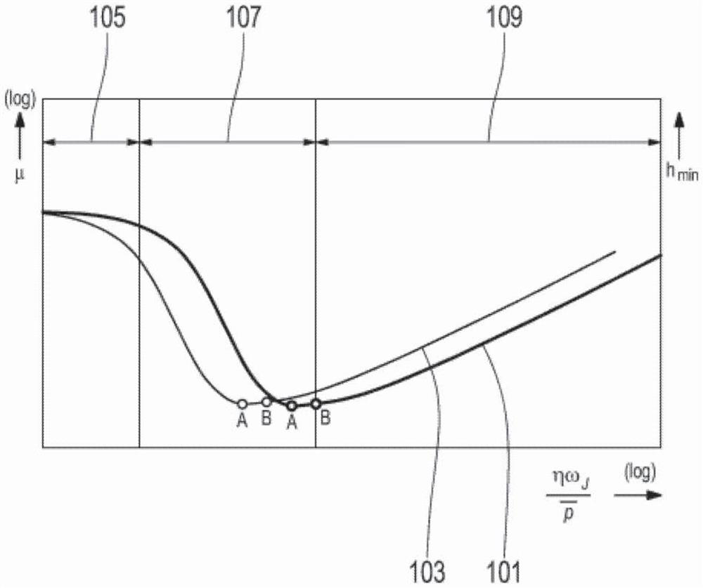
[0022] figure 1 A first Stribeck curve 101 and a second Stribeck curve 103 are shown in . The three operating states of boundary friction 105 , mixed friction 107 and fluid friction 109 are assigned to first Stribeck curve 101 . At the so-called separation point B, the transition from mixed friction 107 to liquid friction 109 occurs. At point A, friction is minimal.

[0023] Through self-healing wear, the first Strybeck curve 101 transforms into a second Strybeck curve. The second Stribeck curve 103 is shifted in the direction of low rotational speed or to the left relative to the first Stribeck curve. Accordingly, points A and B also move. The more movement, ie the greater the spacing between the corresponding points A and B of the first Stribeck curve 101 and the second Stribeck curve 103, the more successful the self-healing. The spacing of the corresponding points A, B of the two Stribeck curves 101 , 103 can thus be used as an indication for the success of self-heali...


PUM


Abstract

The invention relates to a method for operating a sliding bearing, comprising the following steps: ascertaining a first rotational speed at which a change in the lubrication state occurs or at which friction in the sliding bearing is minimal; comparing the first rotating speed with a threshold value; and when the first rotating speed exceeds a threshold value, a self-repairing wear effect occurs in the operation of the sliding bearing.

Description

technical field [0001] The present invention relates to a method according to claim 1 and a controller according to claim 3 . Background technique [0002] Hydrodynamic sliding bearings can operate in different lubrication states. Possible lubrication states are: boundary friction, mixed friction or sliding friction. Transitions between friction states are indistinct. Ideally, hydrodynamic plain bearings operate with sliding friction only. Here, the sliding surfaces are completely separated by a load-bearing lubricating film. In this operating state, no wear occurs. However, in many applications, for example in wind power transmissions, operation with only sliding friction is not possible. If there is boundary friction or mixed friction, the bearing will wear and eventually fail at a later stage of wear. [0003] So-called self-healing wear effects are known from the prior art. Self-healing wear is described, for example, in "Schnell laufende Verbrennungsmaschinen" (H...

Claims


Application Information

Patent Timeline
IPC IPC(8): F16C17/24G01M13/045
CPCF16C17/246F16C2233/00F16C2360/31G01M13/045
Inventor 马尔滕·乌姆斯托马斯·梅内兹罗杰·卡尔
Owner ZF FRIEDRICHSHAFEN AG
Features
  • R&D
  • Intellectual Property
  • Life Sciences
  • Materials
  • Tech Scout
  • Unparalleled Data Quality
  • Higher Quality Content
  • 60% Fewer Hallucinations
Learn More