
Fan impeller dismounting device

A fan impeller and impeller technology, applied in the field of fan impeller removal device, can solve the problems of affecting work efficiency, long heating time of the hub, cumbersome operation of grasping the horse and fixing the impeller, etc., so as to improve work efficiency and facilitate the installation and disassembly of tools Effect

Active Publication Date: 2022-06-28
HUANENG YIMIN COAL POWER CO LTD
View PDF15 Cites 0 Cited by
  • Summary
  • Abstract
  • Description
  • Claims
  • Application Information

AI Technical Summary

Problems solved by technology

[0002] In the current dismantling and maintenance work of the shaft fan in the power plant, the impeller of the shaft fan needs to be dismantled. Due to the long-term operation of the shaft fan, the tight force between the impeller and the motor shaft is too large, and the edge of the wind wheel is used as the stress-bearing part with a crowbar After dismantling, the section of the impeller is thinner and easily deformed under force, which will affect the dynamic balance of the impeller.
The method of dismantling by heating is limited by the large surface area of ​​the impeller, and the heating of the hub takes a long time. Often, the fan shaft and the hub will heat up at the same time, making it impossible to disassemble smoothly.
In the existing technology, it is more common to use a horse to carry out demolition operations, but in actual operation, the fixing operation of the horse and the impeller is relatively cumbersome, which affects work efficiency

Method used


Image

  • Fan impeller dismounting device
  • Fan impeller dismounting device
  • Fan impeller dismounting device

Examples


Embodiment 1

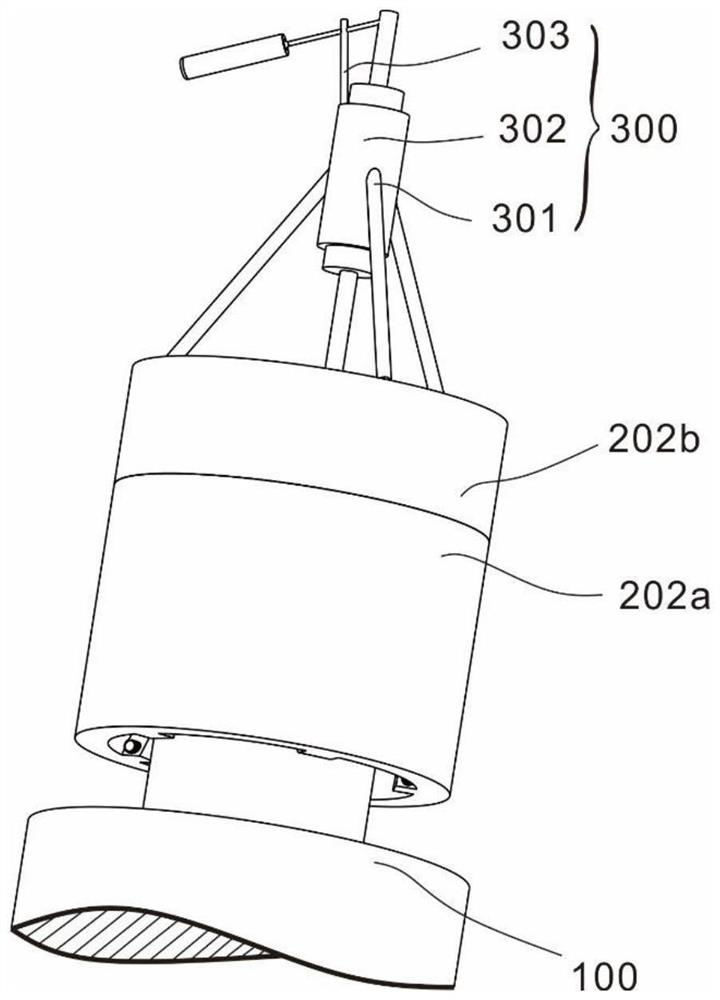
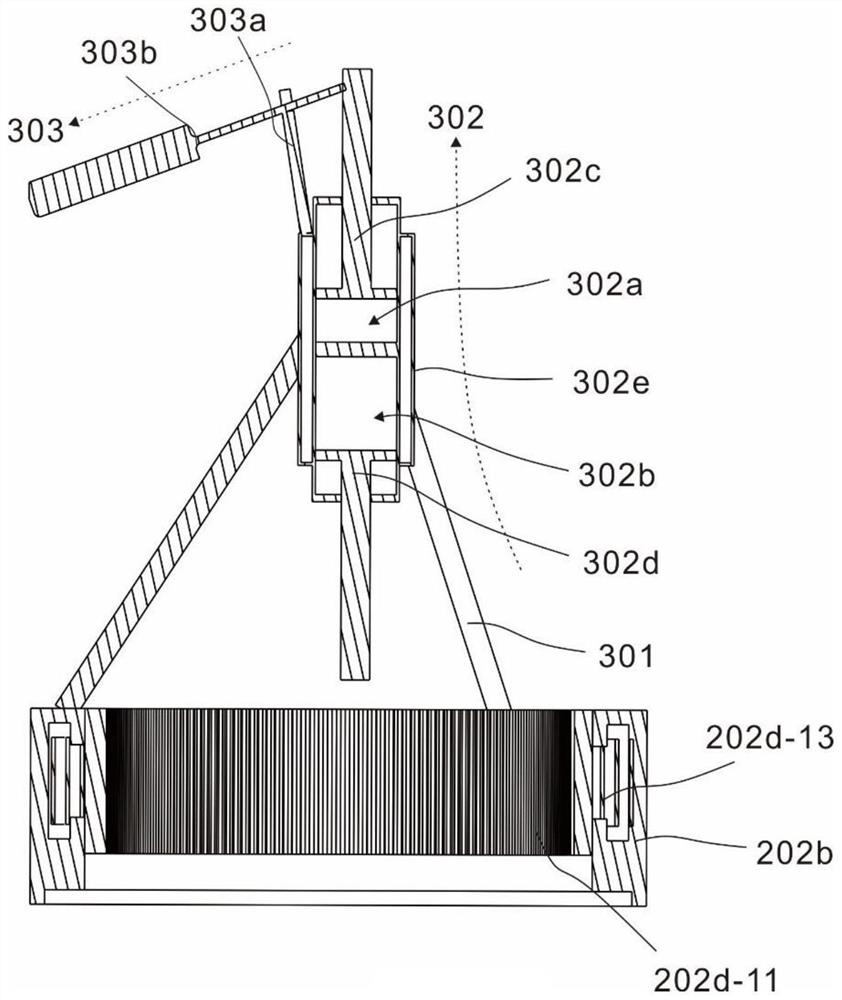
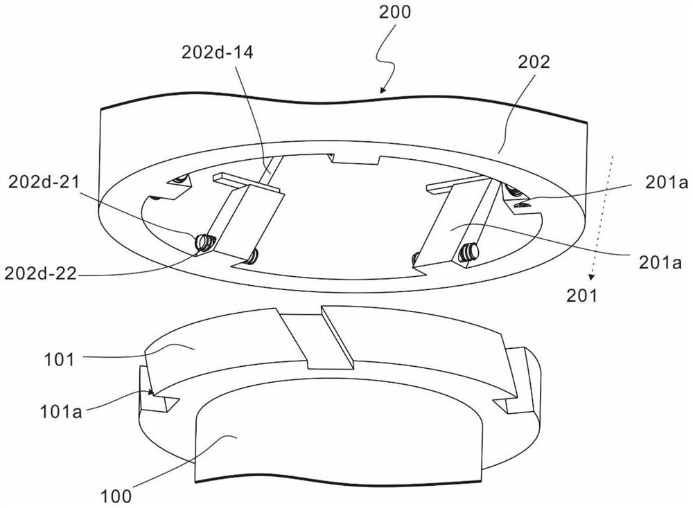
[0027] This embodiment provides a connecting tool for removing the impeller of a shaft-mounted fan, such as Figure 1 to Figure 3 ,

[0028] The device includes an impeller 100, the impeller 100 includes a first connecting piece 101, the first connecting piece 101 is annular, and the first connecting piece 101 is fixed on the upper end of the impeller 100; the connecting piece 200, the connecting piece 200 includes a second connecting member 201 and a rotating assembly 202, the second connecting member 201 is disposed at the lower end of the rotating assembly 202, and the second connecting member 201 is connected with the first connecting member 101; and, the push rod assembly 300, so The push rod assembly 300 is fixed on the rotating assembly 202 .

[0029] The push rod assembly 300 includes a fixed bracket 301 and a pressing mechanism 302 , one side of the fixed bracket 301 is fixedly connected to the side wall of the pressing mechanism 302 , and the other end of the fixed ...

Embodiment 2

[0042] This embodiment provides a connecting tool for removing the impeller of a shaft-mounted fan, such as Figure 1 to Figure 6 On the basis of Embodiment 1, this embodiment is different from Embodiment 1 in that:

[0043] The rotating assembly 202 includes a first drum 202a, a second drum 202b, a one-way mechanism 202c and a locking mechanism 202d. The first drum 202a and the second drum 202b are placed coaxially, and the second drum 202b is located in the first drum. The upper end of the drum 202a is rotatably connected to the first drum 202a, the second connecting piece 201 is arranged on the inner wall of the first drum 202a, the one-way mechanism 202c and the locking mechanism 202d are provided at the connection between the second drum 202b and the first drum 202a. Inside the second drum 202b and the first drum 202a.

[0044] A one-way mechanism 202c is provided at the connection between the second drum 202b and the first drum 202a, so that the relative movement betwee...


PUM


Abstract

The invention provides a fan impeller dismantling device which comprises an impeller, the impeller comprises a first connecting piece, the first connecting piece is in a circular ring shape, and the first connecting piece is fixed to the upper end of the impeller; the connecting part comprises a second connecting piece and a rotating assembly, the second connecting piece is arranged at the lower end of the rotating assembly, and the second connecting piece is connected with the first connecting piece in a matched mode; and the push rod assembly is fixed on the rotating assembly. According to the fan impeller dismantling device, the fan impeller can be efficiently and conveniently dismantled from the shaft, meanwhile, the dismantling tool can be conveniently installed and dismantled, and the working efficiency is improved.

Description

technical field [0001] The invention relates to the technical field of power generation tools, in particular, to a fan impeller removal device. Background technique [0002] In the current disassembly and maintenance work of the shaft-mounted fan in the power plant, the impeller of the shaft-mounted fan needs to be removed. Due to the long-term operation of the shaft-mounted fan, the tight force between the impeller and the motor shaft is too large, and the edge of the wind wheel is used as the force part. When dismantled, the section of the impeller is thin and easily deformed by force, which affects the dynamic balance of the rotor. The method of disassembly by heating is limited by the large surface area of ​​the impeller, and the heating of the hub takes a long time. Often, the fan shaft and the hub heat up at the same time, which cannot be disassembled smoothly. In the prior art, it is common to use a grabber for dismantling operations, but in actual operation, the fix...

Claims


Application Information

Patent Timeline
Patent Type & Authority Applications(China)
IPC IPC(8): B25B27/02
CPCB25B27/026Y02E10/72
Inventor 张延青董泽亮永春崔文喜
Owner HUANENG YIMIN COAL POWER CO LTD
Learn More