Multifunctional mechanical arm type operation device

A technology of multi-functional machinery and working device, applied in the field of robotic arms, which can solve the problems of low degree of freedom, increased working area, and inability to move.

Pending Publication Date: 2022-06-28
CRCC HIGH TECH EQUIP CORP LTD
View PDF0 Cites 0 Cited by
  • Summary
  • Abstract
  • Description
  • Claims
  • Application Information

AI Technical Summary

Problems solved by technology

[0005] The embodiment of the present application provides a multifunctional manipulator-type operating device, aiming at the problem that the current manipulator-type operating equipment has a low degree of freedom and cannot move on a horizontal plane to increase the working area

Method used


Image

  • Multifunctional mechanical arm type operation device
  • Multifunctional mechanical arm type operation device
  • Multifunctional mechanical arm type operation device

Examples


Embodiment 1

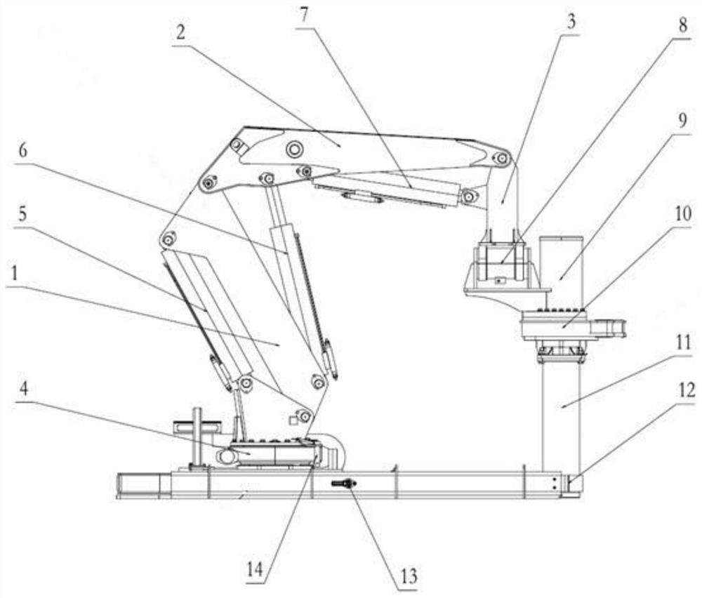
[0045] like figure 1 As shown in the figure, a multifunctional mechanical arm-type working device includes: a sliding mechanism; Movement; working mechanism, installed at the end of the multi-degree-of-freedom robotic arm.

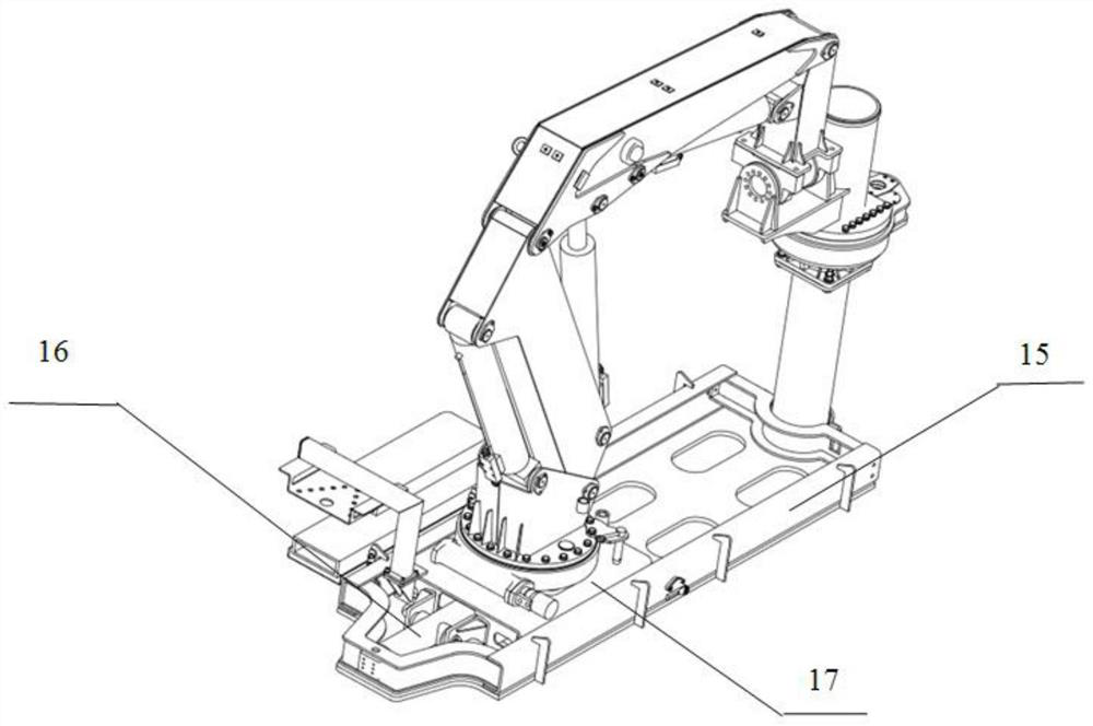
[0046] like figure 1As shown, the multi-degree-of-freedom mechanical arm comprises: the mechanical arm rotating base 4 is connected with the sliding mechanism, and the mechanical arm rotating base 4 can move along the guiding direction of the sliding mechanism, which drives the multi-degree-of-freedom mechanical arm along the sliding mechanism. The guide direction moves; the body of the manipulator is fixed on the rotating base 4 of the manipulator.

[0047] The manipulator rotating base 4 can rotate to drive the manipulator body to rotate.

[0048] like figure 1 As shown, the multi-degree-of-freedom manipulator also includes a primary arm 1, a secondary arm 2 and a tertiary arm 3; wherein: the lower end of the primary arm 1 is hinged with one end of t...

Embodiment 2

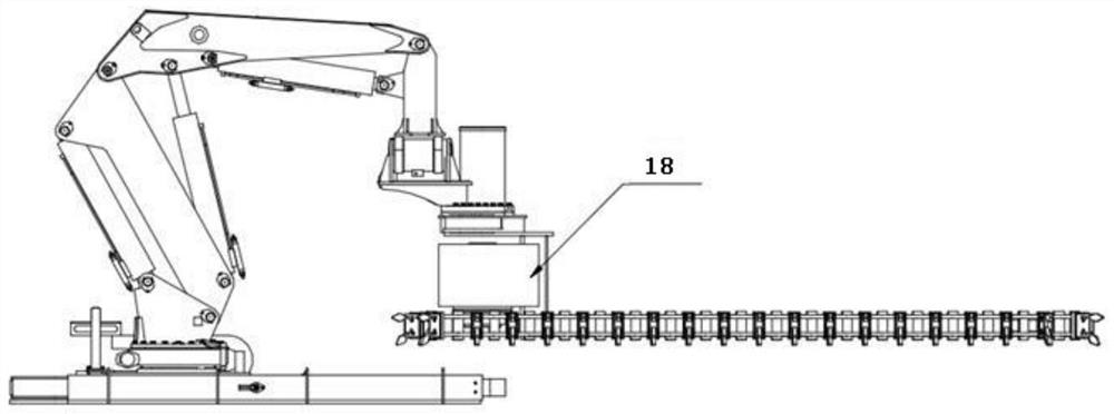
[0056] like figure 1 As shown, a twist suction assembly is provided on the intake end of the bottom of the absorption hard pipe 11 .

[0057] like Figure 4 and Figure 5 As shown, the cutter suction assembly includes a first installation sleeve 19 fitted on the air inlet end of the bottom of the absorption hard pipe 11, and a first blade 20 is symmetrically arranged on the outer wall of the first installation sleeve 19. The first blade 20 is connected to the first blade 20. The outer wall of the installation sleeve 19 is connected by a pin. During operation, the rotating suction head 10 drives the absorption hard tube 11 to rotate, the absorption hard tube 11 drives the first installation sleeve 19 to rotate, and the first installation sleeve 19 drives the first blade 20 on the outer wall. Rotating, the first blade 20 cooperates with the work of the swinging oil cylinder 8 to work on the hardened section, so as to achieve efficient maintenance of heavy-duty railway serious ...

Embodiment 3

[0060] like Image 6 and Figure 7 As shown, the cutter suction assembly includes a second installation sleeve 21 fitted on the air inlet end of the bottom of the absorption hard pipe 11, and a second blade 23 is symmetrically arranged on the outer wall of the second installation sleeve 21. The second blade 23 and the second blade The outer wall of the installation sleeve 21 is fixedly connected.

[0061] like Image 6 and Figure 7 As shown, the second blade 23 is provided with a reinforcing rib plate.

[0062] like Image 6 As shown, a plurality of saw teeth 22 are annularly distributed on the bottom inlet of the second installation sleeve 21 .

[0063] During operation, the rotary suction head 10 drives the absorption hard tube 11 to rotate, the absorption hard tube 11 drives the second installation sleeve 21 to rotate, the second installation sleeve 21 drives the second blade 23 on the outer wall to rotate, and the second blade 23 oscillates with it While the oil cyl...


PUM


Abstract

The embodiment of the invention provides a multifunctional mechanical arm type operation device. The device comprises a sliding mechanism and a mechanical arm, the bottom of the multi-degree-of-freedom mechanical arm is connected with the sliding mechanism, and the multi-degree-of-freedom mechanical arm can move in the guiding direction of the sliding mechanism; and the operation mechanism is mounted at the tail end of the multi-degree-of-freedom mechanical arm. The problems that an existing mechanical arm type operation device is low in freedom degree and cannot move on the horizontal plane to increase the operation area can be solved.

Description

technical field [0001] The present application relates to the technical field of robotic arms, and in particular, to a multifunctional robotic arm-type working device. Background technique [0002] The robotic arm is a new type of device developed in the process of mechanized and automated production. It is mainly used in industrial manufacturing and military fields, while in civilian use, it is mainly concentrated in the medical field. In other fields, such as the field of environmental protection, railway mud and mud remediation, road and ditch cleaning, etc., currently mainly rely on manpower or manpower with machinery. If the robotic arm is used, the demand for construction workers can be reduced, the labor intensity of labor can be reduced, and the operation efficiency can be increased. [0003] However, the current robotic arm-type working equipment has a low degree of freedom and cannot move in a horizontal plane to increase the working area, making the equipment un...

Claims


Application Information

Patent Timeline
Patent Type & Authority Applications(China)
IPC IPC(8): B25J11/00B25J5/02B25J9/14B25J15/00
CPCB25J11/00B25J5/02B25J9/146B25J15/0019B25J15/0066
Inventor 龙绍杭孙荣民普田王成胡春秀
Owner CRCC HIGH TECH EQUIP CORP LTD
Why Eureka
Try Eureka