Supercharge Your Innovation With Domain-Expert AI Agents!

Electronic piling positioning device for building

A positioning device, electronic technology, applied in construction, sheet pile wall, infrastructure engineering and other directions, can solve problems such as inconvenience, and achieve the effect of convenient positioning

Active Publication Date: 2022-06-28
无锡市新兴建筑工程有限公司
View PDF14 Cites 0 Cited by
  • Summary
  • Abstract
  • Description
  • Claims
  • Application Information

AI Technical Summary

Problems solved by technology

[0005] In order to overcome the extremely inconvenient shortcomings of the existing electronic piling positioning device for construction when adjusting the height of the drill pipe, the technical problem of the present invention is to provide an electronic piling positioning device for construction that can easily adjust the height of the piling part

Method used


Image

  • Electronic piling positioning device for building
  • Electronic piling positioning device for building
  • Electronic piling positioning device for building

Examples


Embodiment 1

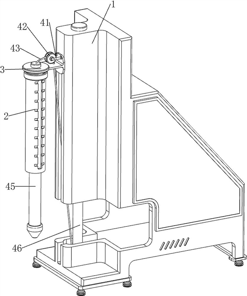
[0033] A building electronic pile driving positioning device, such as Figure 1-2 As shown, it includes a casing 1, a positioning cylinder 2, a sliding sleeve 3, a piling mechanism 4 and an adjusting mechanism 5. The upper left side of the casing 1 is provided with a sliding sleeve 3 through bolts, and the left side of the sliding sleeve 3 is slidably connected with a positioning cylinder 2. A piling mechanism 4 is arranged between the sleeve 3 and the casing 1 for piling positioning, and an adjusting mechanism 5 is arranged on the positioning cylinder 2, which can adjust the depth of piling.

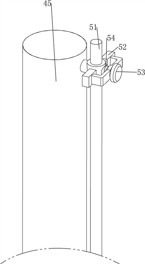
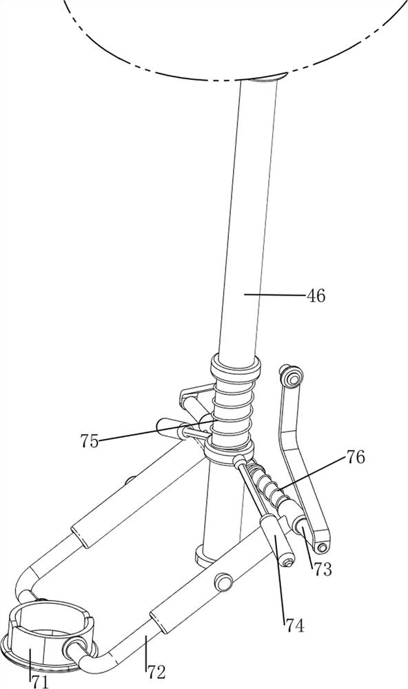
[0034] like image 3 and Figure 4 As shown, the piling mechanism 4 includes a U-shaped rod 41, a guide wheel 42, a pulling rope 43, a piling portion 45 and a cylinder 46, a U-shaped rod 41 is welded on the upper left side of the sliding sleeve 3, and a guide is rotatably connected to the U-shaped rod 41. The wheel 42, the inner and upper side of the casing 1 is provided with a cylind...

Embodiment 2

[0038] On the basis of Example 1, as figure 1 and Figure 7 As shown, a positioning mechanism 6 is also included. The positioning mechanism 6 includes an annular track 61, a fixing sleeve 62, a positioning plate 63 and a torsion spring 64. A fixing sleeve 62 is welded to the lower part of the outer side of the positioning cylinder 2, and the outer side of the fixing sleeve 62 is connected with an annular ring. The track 61, the annular track 61 is connected with a positioning plate 63 in a uniform rotational manner along the circumferential direction, the positioning plate 63 can rotate on the annular track 61, and two torsion springs 64 are arranged between the positioning plate 63 and the annular track 61. Under the action of the torsion spring 64, the positioning plate 63 can be driven to rotate and reset.

[0039] When the positioning cylinder 2 moves downward, it can drive the annular track 61 to move downward, and the downward movement of the annular track 61 drives the p...


PUM


Abstract

The invention relates to a positioning device, in particular to a building electronic piling positioning device. The invention aims to provide the electronic piling positioning device for the building, which can conveniently adjust the height of a piling part. According to the technical scheme, the building electronic piling positioning device comprises a shell, a positioning cylinder, a sliding sleeve, a piling mechanism and an adjusting mechanism, the sliding sleeve is arranged on the upper left side of the shell, the positioning cylinder is arranged on the left side of the sliding sleeve in a sliding mode, the piling mechanism is arranged between the sliding sleeve and the shell, and the adjusting mechanism is arranged on the positioning cylinder. The telescopic rod of the air cylinder can drive the pull rope to be loosened, under the gravity action of the piling part and the positioning barrel, the positioning barrel and the piling part rapidly move downwards, the piling part can be inserted into soil when moving downwards, and therefore the piling positioning effect can be achieved.

Description

technical field [0001] The invention relates to a positioning device, in particular to a building electronic pile driving positioning device. Background technique [0002] In the process of building construction, in order to be able to carry out more stable construction of the building, it is necessary to carry out electronic piling positioning. [0003] The patent application number is CN202020919951.X An electronic piling positioning device for construction, including a base plate, a driving motor and a drill pipe, a roller is installed on the base plate, a vertical equipment rack is installed on the base plate, and a sleeve is sleeved on the equipment rack. There is a movable sleeve, one side of the movable sleeve is fixedly connected with a mounting plate, the driving motor is fixedly installed on the top wall of the mounting plate, and the driving shaft of the driving motor extends to the lower side of the mounting plate and is fixedly connected with a drill. A movable...

Claims


Application Information

Patent Timeline
Patent Type & Authority Applications(China)
IPC IPC(8): E02D7/06E02D7/08E02D7/14E02D7/16E02D13/04
CPCE02D7/06E02D7/14E02D7/16E02D7/08E02D13/04Y02E10/50
Inventor 李学顺
Owner 无锡市新兴建筑工程有限公司
Features
  • R&D
  • Intellectual Property
  • Life Sciences
  • Materials
  • Tech Scout
  • Unparalleled Data Quality
  • Higher Quality Content
  • 60% Fewer Hallucinations
Learn More