Pulse recognition method and device, storage medium, equipment and blood cell analyzer

An identification method and pulse technology, applied in measuring devices, analysis materials, individual particle analysis, etc., can solve the problems of abnormal measured values, increased costs, and high requirements for optical components, and achieve the effects of increasing costs, improving accuracy, and saving resources

Pending Publication Date: 2022-06-28
MACCURA MEDICAL INSTR CO LTD
View PDF17 Cites 0 Cited by
  • Summary
  • Abstract
  • Description
  • Claims
  • Application Information

AI Technical Summary

Problems solved by technology

For example, when measuring platelets, the above-mentioned side lobes will be divided into platelet cells, resulting in high platelet measurement values ​​by optical methods
[0004] This problem can fundamentally remove sidelobe interference by changing optical devices, but the requirements for optical components are high, which will increase the cost; linear correction can also be used to compensate for the misidentification of high and low value samples and the number of missed identification cells. This method is relatively simple, but it does not solve the problem from the source, but only adjusts the final value, so the measured value is not accurate enough, and the measured value of some samples may appear obviously abnormal

Method used


Image

  • Pulse recognition method and device, storage medium, equipment and blood cell analyzer
  • Pulse recognition method and device, storage medium, equipment and blood cell analyzer
  • Pulse recognition method and device, storage medium, equipment and blood cell analyzer

Examples


Embodiment 1

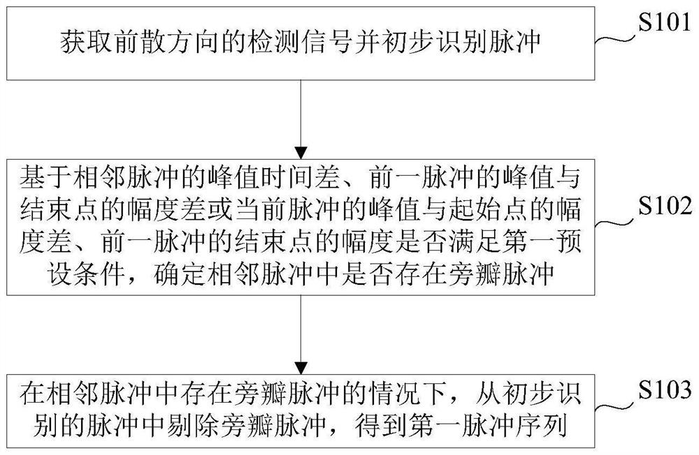
[0057] figure 1 A flow chart of a pulse identification method is shown, such as figure 1 As shown, the pulse identification method provided in this embodiment includes steps S101 to S103:

[0058] Step S101 , acquiring the detection signal of the forward dispersion direction and preliminarily identifying the pulse.

[0059] Step S102, based on whether the peak time difference of adjacent pulses, the amplitude difference between the peak value of the previous pulse and the end point or the amplitude difference between the peak value and the start point of the current pulse, and the amplitude of the end point of the previous pulse meet the first preset condition, Determine whether there are sidelobe pulses in adjacent pulses;

[0060] Step S103 , in the case that there are side lobe pulses in adjacent pulses, remove the side lobe pulses from the preliminarily identified pulses to obtain a first pulse sequence.

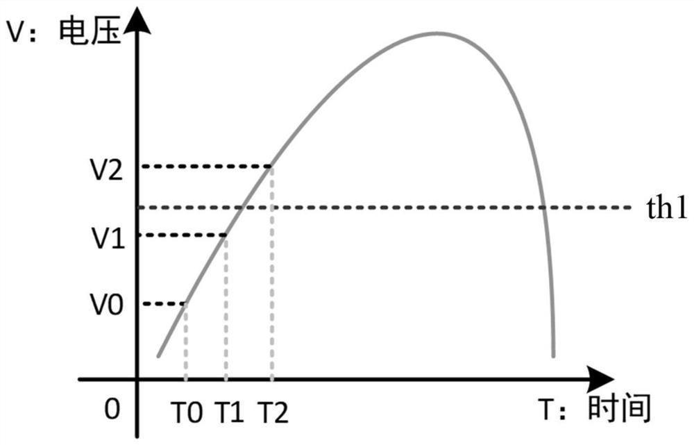
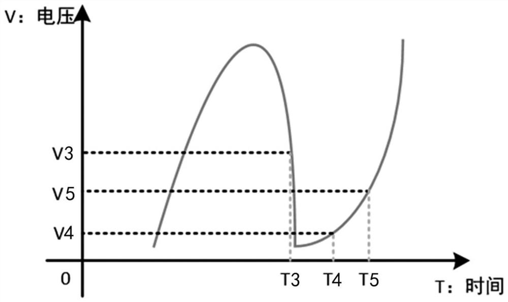
[0061] In this embodiment, the detection signal in the forward s...

Embodiment 2

[0107] Figure 12 A block diagram of a pulse identification device is shown, such as Figure 12 As shown, this embodiment provides a pulse identification device, including:

[0108] The pulse identification module 201 is used to acquire the detection signal of the forward dispersion direction and initially identify the pulse;

[0109] The side lobe removal module 202 is used for whether based on the peak time difference of adjacent pulses, the amplitude difference between the peak value of the previous pulse and the ending point or the amplitude difference between the peak value and the starting point of the current pulse, and the amplitude of the ending point of the previous pulse. A preset condition is to determine whether there are side lobe pulses in adjacent pulses; if there are side lobe pulses in adjacent pulses, remove the side lobe pulses from the preliminarily identified pulses to obtain a first pulse sequence.

[0110] In this embodiment, the detection signal in t...

Embodiment 3

[0136] This embodiment provides a computer-readable storage medium. The computer-readable storage medium stores a computer program. When the computer program is executed by one or more processors, the pulse identification method provided in the first embodiment is implemented.

[0137] In this embodiment, the storage medium may be implemented by any type of volatile or nonvolatile storage device or a combination thereof, such as static random access memory (Static Random Access Memory, SRAM for short), electrically erasable programmable Read-Only Memory (Electrically Erasable Programmable Read-Only Memory, EEPROM for short), Erasable Programmable Read-Only Memory (EPROM for short), Programmable Read-Only Memory (PROM for short) ), read-only memory (Read-Only Memory, ROM for short), magnetic memory, flash memory, magnetic disk or optical disk. The content of the method is detailed in Embodiment 1, which will not be repeated this time.


PUM


Abstract

The invention provides a pulse recognition method and device, a storage medium, equipment and a blood cell analyzer. The pulse identification method comprises the following steps: acquiring a detection signal in a forward scattering direction and preliminarily identifying a pulse; determining whether there is a sidelobe pulse in the adjacent pulses based on whether the peak value time difference of the adjacent pulses, the amplitude difference between the peak value of the previous pulse and the end point or the amplitude difference between the peak value of the current pulse and the starting point, and the amplitude of the end point of the previous pulse satisfy a first preset condition; under the condition that the sidelobe pulses exist in the adjacent pulses, the sidelobe pulses are removed from the preliminarily recognized pulses, and a first pulse sequence is obtained. According to the invention, the influence of optical sidelobe on platelet counting can be removed from the pulse identification stage, and the cost does not need to be increased.

Description

technical field [0001] The present invention relates to the technical field of blood cell detection, in particular to a pulse identification method, device, storage medium, equipment and blood cell analyzer. Background technique [0002] There are two main methods for blood cell detection in the blood cell analyzer: one is the impedance method, and the other is the optical method. Most of the early blood analyzers used the impedance method to measure blood cells. The specific principle of the impedance method is Coulter's principle, which uses the change of impedance at both ends of the small hole when blood cells flow through the small hole for detection. With the advancement of cell detection technology, the optical method has emerged. Realize the detection of blood cells. Compared with the traditional impedance method, the optical method is more sensitive in detecting blood cells, less affected by the blood sample, and more accurate. Therefore, high-end blood cell anal...

Claims


Application Information

Patent Timeline
Patent Type & Authority Applications(China)
IPC IPC(8): G01N15/10
CPCG01N15/10G01N2015/1006
Inventor 张馨月郭煜飞余江琦赵清楠颜军琳
Owner MACCURA MEDICAL INSTR CO LTD
Why Eureka
Try Eureka