Upper limb training mechanism for rehabilitation patient

A technology for training institutions and patients, applied in passive exercise equipment, physical therapy and other directions, it can solve the problems of wrist injury, loss of equipment, heavy equipment, etc., and achieve the effect of avoiding bump damage and high flexibility

Pending Publication Date: 2022-07-01
河南省儿童医院郑州儿童医院
0 Cites 0 Cited by

AI-Extracted Technical Summary

Problems solved by technology

[0002] When clinical patients undergo postoperative rehabilitation, due to weak limb strength and different limb strength conditions of different patients, professional rehabilitation teachers are required to supervise and assist in real time during rehabilitation training to avoid secondary damage to patients by equipment. For example, in the recovery training of the upper limbs, when some patients lift or stretch upwards, they have insufficient grip and the proble...

Method used

The protective wrist 101 can rotate around the grip shaft 104, and the inner ring 102 and the outer ring 2021 are connected similarly to a ball hinge, so the protective wrist 101 can rotate...

Abstract

The invention discloses an upper limb training mechanism for a rehabilitation patient. The upper limb training mechanism comprises a holding part, a transverse adjusting part and a vertical lifting part, the vertical lifting part comprises a sliding block body capable of vertically sliding up and down, a torque sensor used for detecting external lifting force received by the sliding block body, and a driving motor used for driving the sliding block body to slide up and down according to a detection value of the torque sensor; transverse adjusting parts capable of swinging around the Z axis are arranged on the two sides of the sliding block body respectively, and a damping mechanism for adjusting the swinging resistance of the transverse adjusting parts is arranged in the sliding block body. The transverse adjusting part comprises a transverse sliding rod rotating along the axis Z. The upper limb training mechanism for the rehabilitation patient integrates multiple upper limb training modes, effectively protects the position, prone to being injured, of the patient, simulates a professional rehabilitation technician to conduct rehabilitation training on the patient through own power, effectively improves the training effect and shortens the rehabilitation period.

Application Domain

Chiropractic devices

Technology Topic

Electric machineryTraining effect +5

Image

  • Upper limb training mechanism for rehabilitation patient
  • Upper limb training mechanism for rehabilitation patient
  • Upper limb training mechanism for rehabilitation patient

Examples

  • Experimental program(1)

Example Embodiment

[0027] The technical solutions in the embodiments of the present invention will be clearly and completely described below with reference to the accompanying drawings in the embodiments of the present invention. Obviously, the described embodiments are only a part of the embodiments of the present invention, but not all of the embodiments. Based on the embodiments of the present invention, all other embodiments obtained by those of ordinary skill in the art without creative efforts shall fall within the protection scope of the present invention.
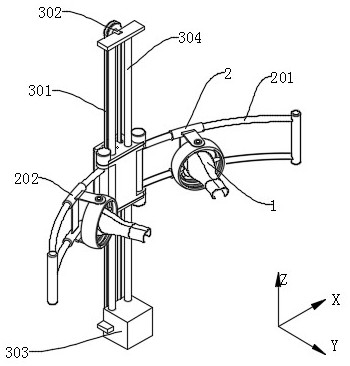
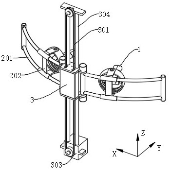
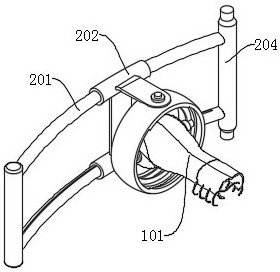
[0028] see Figure 1-Figure 9 , the present invention provides a technical solution: an upper limb training mechanism for rehabilitation patients, comprising a holding part 1, a lateral adjustment part 2 and a vertical lifting part 3;
[0029] The vertical lifting part 3 includes a slider body 305 that can slide vertically up and down, a torque sensor 302 for detecting that the slider body 305 receives an external lifting force, and drives the slider body 305 to slide up and down according to the detected value of the torque sensor 302 The drive motor 303; the two sides of the slider body 305 are respectively provided with a lateral adjustment part 2 that can swing around the Z axis, and the slider body 305 is provided with a damping mechanism for adjusting the swing resistance of the lateral adjustment part 2;
[0030] The lateral adjustment part 2 includes a lateral slide bar 201 that rotates with the slider body 305 along the Z axis, a mounting seat 202 that is slidably installed with the lateral slide bar 201 in the horizontal direction, and is arranged between the mounting seat 202 and the lateral slide bar 201 along the sliding direction elastic band 203;
[0031] see Image 6 and Figure 7 , the grip 1 includes a protective wrist 101 for protecting the patient's hand, the protective wrist 101 includes a hard guard 1012 capable of externally protecting the patient's fist and wrist, and the inside of the front end is provided with a grip for the patient's hand The holding sleeve 1011 is held, and the rear is provided with a flexible protection 1013 for wrapping and fixing the patient's small arm; the protection wrist 101 and the mounting seat 202 are installed in a ball hinge manner, and the mounting seat 202 is provided with an adjustment protection wrist 101 Rotation resistance damping mechanism;
[0032] In actual use, the patient can hold the holding sleeve 1011 with the hand, and the forearm is wrapped by the flexible guard 1013 and bound by the restraint strap 1014, which can effectively prevent the instrument from falling off due to muscle weakness, and the hard guard 1012 at the front end It can effectively prevent the patient's hand bump injury.
[0033] see Image 6 , the holding part 1 also includes an inner ring 102, the outer ring surface of the inner ring 102 is a spherical surface, and a holding shaft 104 is fixed radially in the middle, the holding sleeve 1011 is rotatably sleeved outside the holding shaft 104, and holds A locking sleeve 103 is provided on the outside of the shaft 104 through a thread, and the locking sleeve 103 can be rotated to generate an axial displacement, thereby clamping the protective wrist 101 from both ends and restraining the relative rotation of the protective wrist 101 and the holding shaft 104; the mounting seat 202 includes an outer ring 2021 whose inner surface is a spherical surface, and the spherical surfaces of the inner ring 102 and the outer ring 2021 are slidably installed;
[0034] The protective wrist 101 can rotate around the holding shaft 104, and the inner ring 102 and the outer ring 2021 are connected like a ball hinge, so the protective wrist 101 can rotate 360° relative to the mounting seat 202, which has a high degree of freedom and flexibility, and is suitable for upper limbs Hand holding posture in different rehabilitation training situations.
[0035] see Figure 8, the outer ring surface of the inner ring 102 is provided with an annular limit groove 1021, the axis of the limit groove 1021 is consistent with the axis of the inner ring 102, and the limit hole 1022 is evenly arranged at the bottom of the limit groove 1021, and the axis of the limit hole 1022 is perpendicular to the inner ring 102 axis, the outer ring 2021 is fixed with an electromagnetic pin 2023 that can expand and contract in the radial direction. When the electromagnetic pin 2023 is retracted, the pin body of the electromagnetic pin 2023 can slide in the limit groove 1021. When the electromagnetic pin 2023 extends , the pin body can penetrate the limit hole 1022 at the corresponding position;
[0036] When performing part of the upper limb training, it is necessary to limit part of the freedom of movement of the hand, so as to ensure that the hand of the patient with muscle weakness can have a proper posture and avoid sprains. When the electromagnetic pin 2023 is extended, it can effectively limit the inner ring 102 and the outer ring. The rotation of the ring 2021 , that is, the inner ring 102 and the outer ring 2021 can only rotate around the axis of the pin body of the electromagnetic pin 2023 .
[0037] see Figure 4 , the transverse sliding rod 201 includes a vertical rotating shaft 204 overlapping with its own rotation axis, the slider body 305 is provided with a piston body 306 driven by an external hydraulic pressure, and the piston body 306 can clamp the vertical rotating shaft 204 from the end, thereby adjusting Its rotational resistance; the piston body 306 and the slider body 305 are slidably installed along the vertical axis, and a tapered surface capable of mutual contact and friction is provided between the vertical shaft 204 and the piston body 306;
[0038] Through the pressurized movement of the piston body 306, the friction force between it and the vertical shaft 204 is changed, so as to adjust the driving force required for the swing of the lateral sliding rod 201, and increase the distance for detecting the position of the mounting seat 202 at the end of the lateral sliding rod 201 The sensor determines the distance between the mounting seat 202 and the vertical shaft 204, that is, measures the moment arm, and adjusts the damping force of the lateral slide bar 201 according to the size of the moment arm, so as to obtain the best damping force required for rehabilitation training.
[0039] see Figure 5 , the vertical lifting part 3 includes fixed runners at the top and bottom, a torque sensor 302 is arranged in the fixed runner mounting seat on the top, the driving motor 303 drives the fixed runner at the bottom, and a synchronizing wheel is set between the two sets of fixed runners The toothed belt 301 and the slider body 305 are fixedly connected with the loose side of the synchronous toothed belt 301;
[0040] The synchronous toothed belt 301 is driven to rotate by the drive motor 303, which drives the slider body 305 to move up and down, and when the patient performs a lifting motion, the torque sensor 302 controls the drive force of the drive motor 303 according to the measured force reduction, that is, when When the patient has a large lifting force, a small traction force is allocated to the driving motor 303. When the patient has a small lifting force, a large traction force is allocated to the driving motor 303 to ensure that the slider body 305 is under the action of the patient lifting. , can effectively slide, improve the patient's self-confidence in rehabilitation, and when the patient's lifting force is extremely small, the slider body 305 can be driven up and down through the driving motor 303, and the patient's upper limbs can be driven to lift the upper limbs in the opposite direction.
[0041] Vertically arranged vertical sliding rods 304 are used, the slider body 305 is slidably installed with the vertical sliding rods 304, the fixed wheels are respectively arranged at both ends of the vertical sliding rods 304, and the horizontal sliding rods 201 adopt an arc structure, which is installed The seat 202 also includes a sliding sleeve 2022 fixed with the outer ring 2021. The curvature of the sliding sleeve 2022 is consistent with the lateral sliding rod 201, and the lateral sliding rod 201 is a hollow shaft. The elastic band 203 is built in the lateral sliding rod 201. The side wall of 201 is provided with a long groove, and the sliding sleeve 2022 is partially inside the lateral sliding rod 201 through the long groove, and is connected with the elastic band 203, so that the mounting seat 202 has a certain resistance when sliding.
[0042] The grip portion 1 designed in the present invention can provide relatively good protection for the patient's hand, wrist and forearm position, and has a high degree of freedom, and can limit different degrees of freedom through different damping adjustment methods. The damping strength changes the damping required for its rotation to ensure the correct posture during the exercise process, and can drive the hydraulic power output by pre-programming and controlling the drive motor 303 and the piston body 306, and rely on external forces to assist the simulation of professional rehabilitation coaches to help patients. Self-rehabilitation training.
[0043] Although embodiments of the present invention have been shown and described, it will be understood by those skilled in the art that various changes, modifications, and substitutions can be made in these embodiments without departing from the principle and spirit of the invention and modifications, the scope of the present invention is defined by the appended claims and their equivalents.

PUM

no PUM

Description & Claims & Application Information

We can also present the details of the Description, Claims and Application information to help users get a comprehensive understanding of the technical details of the patent, such as background art, summary of invention, brief description of drawings, description of embodiments, and other original content. On the other hand, users can also determine the specific scope of protection of the technology through the list of claims; as well as understand the changes in the life cycle of the technology with the presentation of the patent timeline. Login to view more.

Similar technology patents

Buffering type steel wire rope stranding device

PendingCN110791986AAvoid bump damagequality improvement
Owner:江苏艾可森钢绳有限公司

Server placing device

PendingCN113905574AAvoid bump damageavoid shaking or tipping
Owner:国家电网有限公司客户服务中心

Special vibration-proof trolley for bricks and tiles

InactiveCN105882710Agood shock absorberAvoid bump damage
Owner:无锡瑾宸表面处理有限公司

Multi-module combined PACK box body and battery pack matching method

PendingCN113314796AAvoid bump damageGood cooling effect
Owner:江苏润寅石墨烯科技有限公司

Storage box

PendingCN111756968AAvoid bump damageEasy to store
Owner:SHANGHAI MOSHON TECH CO LTD

Classification and recommendation of technical efficacy words

  • Avoid bump damage
  • High flexibility

Lubricating oil-way of engine cylinder assembly

InactiveCN1786449AAvoid bump damageBeautiful structural design
Owner:CHERY AUTOMOBILE CO LTD

Hospital disinfection device

ActiveCN111437410AImprove disinfection efficiencyAvoid bump damage
Owner:QINGDAO WOMEN & CHILDREN HOSPITAL

Vertical automobile exhaust gas remote sensing monitoring device

PendingCN109709284AAvoid bump damageeasy to use
Owner:REED XINXIANG ROAD INC

Special vibration-proof trolley for bricks and tiles

InactiveCN105882710Agood shock absorberAvoid bump damage
Owner:无锡瑾宸表面处理有限公司

Buffering type steel wire rope stranding device

PendingCN110791986AAvoid bump damagequality improvement
Owner:江苏艾可森钢绳有限公司

Indwelling implant for embolization

InactiveUS20060116708A1high flexibilitysafe operation
Owner:KANEKA CORP +1

Memory controller

ActiveCN101702326Alow costHigh flexibility
Owner:DAWNING INFORMATION IND BEIJING +1

Self-reducing, cold-bonded pellets

ActiveUS20050061207A1lower production costhigh flexibility
Owner:HANQING LIU
Why Eureka
Try Eureka