
Sprue spreader cooling structure

A cooling structure and diverter cone technology, applied in the field of diverter cones, can solve the problems of not installing a cleaning device, affecting the diversion of the diverter cone to the molten metal, and uneven cooling

Pending Publication Date: 2022-07-01
上海胜桀精密机械科技有限公司
View PDF0 Cites 0 Cited by
  • Summary
  • Abstract
  • Description
  • Claims
  • Application Information

AI Technical Summary

Problems solved by technology

[0004] 1. The traditional cooling structure of the splitter cone is not equipped with a cleaning device. When the splitter cone is in use, impurities and solidified molten metal will remain on the surface of the splitter cone, which will affect the flow of the molten metal by the splitter cone.
[0005] 2. The traditional split cone cooling structure cannot be used for circulating cooling, and there will be uneven cooling during cooling

Method used


Image

  • Sprue spreader cooling structure
  • Sprue spreader cooling structure
  • Sprue spreader cooling structure

Examples


Embodiment Construction

[0022] The technical solutions in the embodiments of the present invention will be clearly and completely described below with reference to the accompanying drawings in the embodiments of the present invention. Obviously, the described embodiments are only a part of the embodiments of the present invention, but not all of the embodiments. Based on the embodiments of the present invention, all other embodiments obtained by those of ordinary skill in the art without creative efforts shall fall within the protection scope of the present invention.

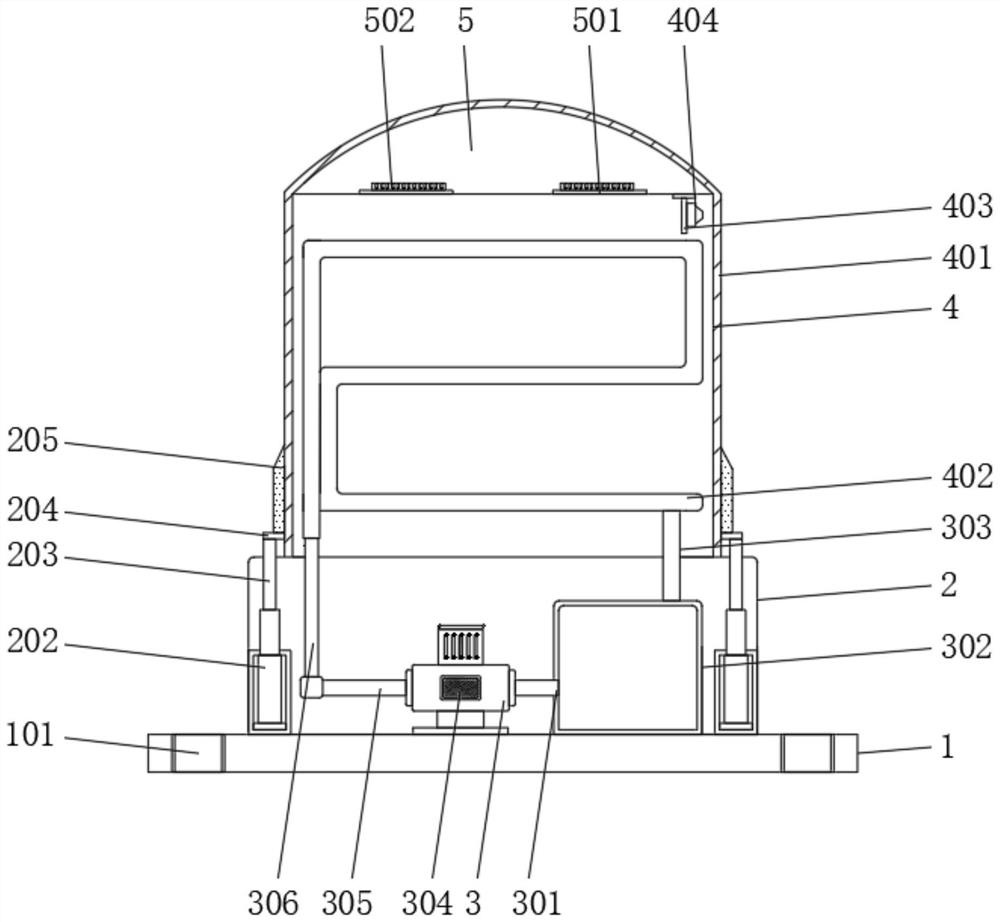
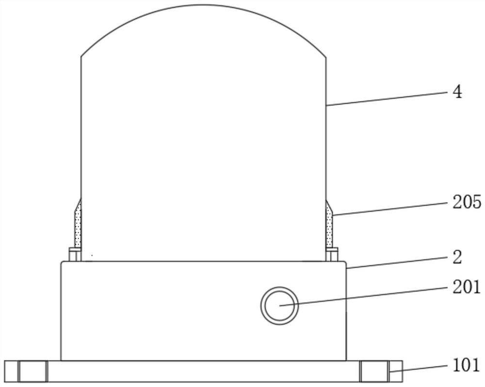
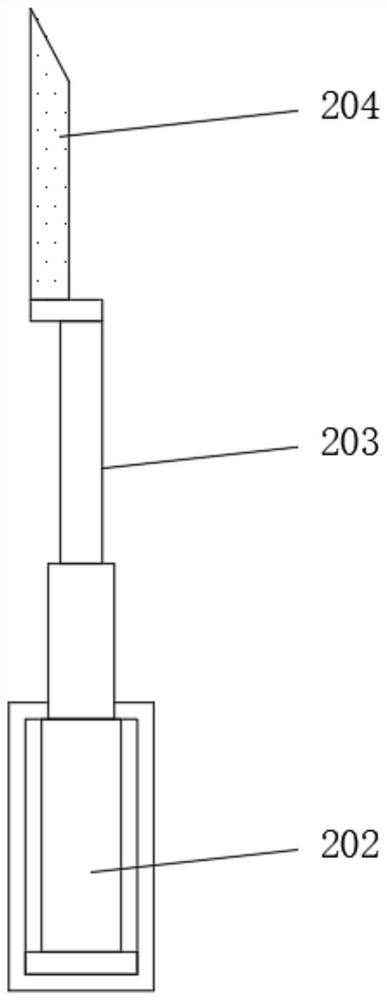
[0023] see Figure 1-5 , an embodiment provided by the present invention: a shunt cone cooling structure, comprising a base 1, a miniature water pump 3 and a shunt cone body 4, characterized in that: the top of the base 1 is installed with an installation box 2, and the front of the installation box 2 is installed There is a liquid inlet 201, a hydraulic cylinder 202 is installed on the bottom inner wall of the installation box 2, the...


PUM


Abstract

The sprue spreader cooling structure comprises a base, a micro water pump and a sprue spreader body, a mounting box is mounted at the top of the base, a liquid inlet is formed in the front face of the mounting box, a hydraulic cylinder is mounted on the inner wall of the bottom of the mounting box, and the micro water pump is mounted on the inner wall of the bottom of the mounting box; and the micro water pump is located on one side of the hydraulic cylinder, a sprue spreader body is mounted at the top of the mounting box, and a mounting groove is formed in the top of the sprue spreader body. The cleaning device is mounted on the outer side of the sprue spreader body, and a cleaning plate can move up and down on the surface of the sprue spreader through a hydraulic cylinder in the cleaning device, so that the effect of cleaning impurities and solidified molten metal on the surface of the sprue spreader is achieved, and the surface of the sprue spreader body is cleaner; and the influence on the shunting of the molten metal in the straight flow pipe due to the residual impurities on the surface is avoided, so that the shunting cone body can work better.

Description

technical field [0001] The invention relates to the technical field of flow splitting cones, in particular to a flow splitting cone cooling structure. Background technique [0002] The diverter cone is used to divert the flow. It needs to divert the molten metal with very high heat, so the cooling structure is an indispensable structure. Through the cooling structure, the diverter cone can be cooled to prevent the diverter cone from being used. , because the heat is too high to cause damage to the split cone, the existing cooling structure cannot perform circulating cooling, and the cooling will be uneven during cooling. [0003] The defects of the existing split cone cooling structure are: [0004] 1. The traditional shunt cone cooling structure is not equipped with a cleaning device. When the shunt cone is in use, impurities and solidified metal liquid will remain on the surface of the shunt cone, which will affect the shunt cone to shunt the metal liquid. [0005] 2. Th...

Claims


Application Information

Patent Timeline
Patent Type & Authority Applications(China)
IPC IPC(8): B22C9/08B22D46/00B08B1/00
CPCB22C9/08B22D46/00B08B1/30
Inventor 吴海燕
Owner 上海胜桀精密机械科技有限公司
Learn More