
Combined fan device

A combined, fan technology, applied in pump devices, components of pumping devices for elastic fluids, non-variable-capacity pumps, etc., can solve problems such as unseen, and achieve the effect of reducing manufacturing costs

Pending Publication Date: 2022-07-01
YIWU DINGBANG STATIONERY & SPORTING GOODS
View PDF0 Cites 0 Cited by
  • Summary
  • Abstract
  • Description
  • Claims
  • Application Information

AI Technical Summary

Problems solved by technology

[0005] In the market and relevant literature, there is no combination of the two

Method used


Image

  • Combined fan device
  • Combined fan device
  • Combined fan device

Examples


Embodiment Construction

[0034] Preferred embodiments of the present invention will be described in detail below with reference to the accompanying drawings. Those skilled in the art will appreciate that these descriptions are descriptive, exemplary only, and should not be construed as limiting the scope of protection of the present invention.

[0035] It should be noted that like numerals refer to like items in the following figures, so once an item is defined in one figure, it may not be further defined and explained in subsequent figures.

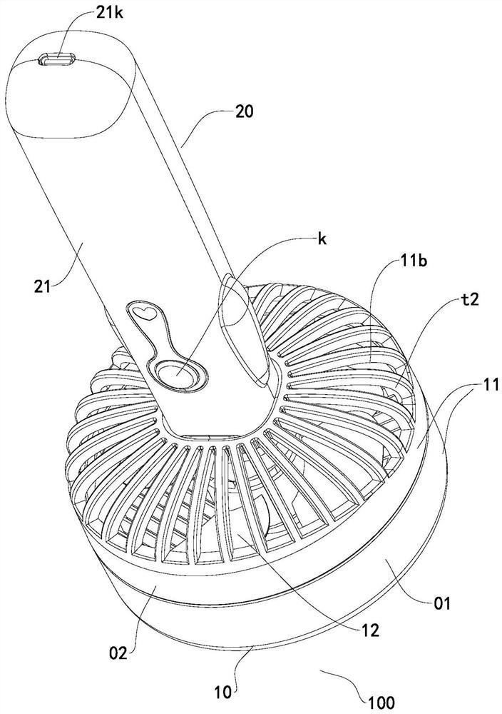
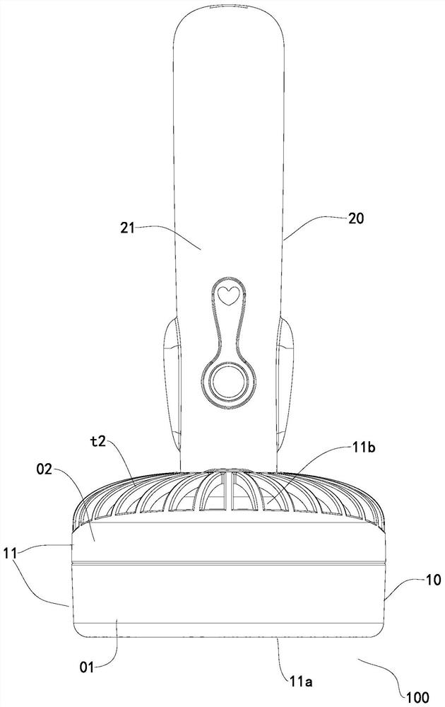
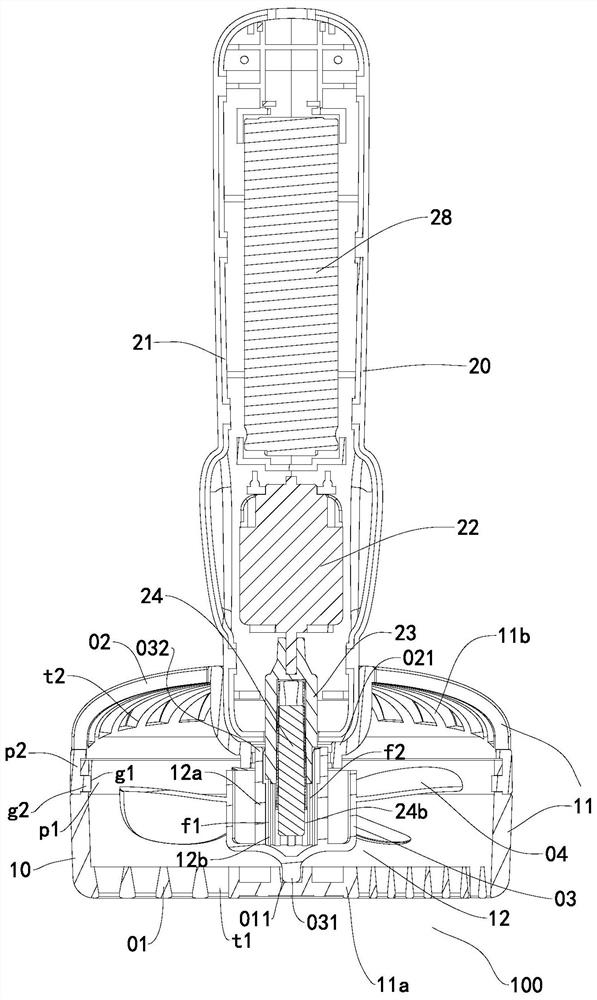
[0036] like Figure 1 to Figure 4 As shown, the combined fan device 100 includes a fan unit 10 and a drive unit 20; the fan unit 10 includes a first casing 11 and an impeller 12 located in the first casing 11, and the first casing 11 is provided with an air inlet 11a and the air outlet 11b; the drive unit 20 includes a second casing 21, a motor 22 and a drive shaft 23; the front end of the drive shaft 23 protrudes out of the second casing 21 to form a drive hea...


PUM


Abstract

The invention discloses a combined fan device which comprises a fan unit and a driving unit. The fan unit comprises a first shell and an impeller located in the first shell, and an air inlet and an air outlet are formed in the first shell. The driving unit comprises a second shell, a motor and a driving shaft; the front end of the driving shaft extends out of the second shell to form a driving head, and the driving head penetrates into the first shell to be connected with the impeller. The motor drives the impeller to rotate through the driving shaft; a driving shaft of the driving unit drives an impeller in the fan unit to rotate, so that the fan unit has an air blowing effect; the fan unit is powered by the driving unit, so that electronic components such as a motor and a switch can be omitted, and the fan unit can be directly cleaned with water; a motor and the like are omitted in the fan unit, so that the overall manufacturing cost of the fan unit and the fan unit is reduced; meanwhile, the driving unit is inserted into the fan unit, the entertainment effect of an assembling tool is achieved, and the fan can be loved and welcomed by students or office workers.

Description

technical field [0001] The present invention relates to a fan, in particular to a combined fan device. Background technique [0002] The electric eraser is driven by a motor to rotate the eraser for erasing pencil words. [0003] Handheld fan, easy to be small and portable, can be used at home or when traveling in hot summer. It includes a handle and a fan body at one end of the handle. The fan body includes a casing and a fan blade in the casing, and a motor for driving the fan blade to rotate is usually arranged in the handle. [0004] The multi-purpose electric eraser with the publication number of CN2169555Y discloses that a micro-motor is arranged in the casing, a transmission wheel is arranged on the outlet shaft of the micro-motor, a passive wheel is arranged corresponding to the traditional wheel, and the eraser head is arranged on the passive wheel . [0005] There is no combination of the two in the market and related literature. SUMMARY OF THE INVENTION [0...

Claims


Application Information

Patent Timeline
IPC IPC(8): F04D25/08F04D29/00F04D29/64
CPCF04D25/08F04D29/002F04D29/646
Inventor 金响标
Owner YIWU DINGBANG STATIONERY & SPORTING GOODS
Learn More