Piston rod cavity oil storage oil cylinder

A technology in piston rods and piston rods, applied in the direction of fluid pressure actuation devices, etc., can solve the problems of affecting the quality of oil cylinders and increasing friction, and achieve the effects of reducing weight, reducing friction, and increasing guide length

Pending Publication Date: 2022-07-01
XUZHOU YANHUANG ENG MACHINERY
View PDF0 Cites 0 Cited by
  • Summary
  • Abstract
  • Description
  • Claims
  • Application Information

AI Technical Summary

Problems solved by technology

In the traditional hydraulic cylinder, the welding deformation zone of the rod block at the outer piston rod extends to the piston part after the cylinder is fully extended, resulting in increased friction and affecting the use quality of the cylinder

Method used


Image

  • Piston rod cavity oil storage oil cylinder

Examples


Embodiment Construction

[0027] The technical solutions in the embodiments of the present invention will be clearly and completely described below with reference to the accompanying drawings in the embodiments of the present invention.

[0028] The invention provides a piston rod cavity oil storage cylinder. The purpose is to facilitate disassembly, reduce the friction between the piston and the cylinder, and lift the quality of the cylinder.

[0029] The present invention will be further described in detail below in conjunction with the examples and specific implementations.

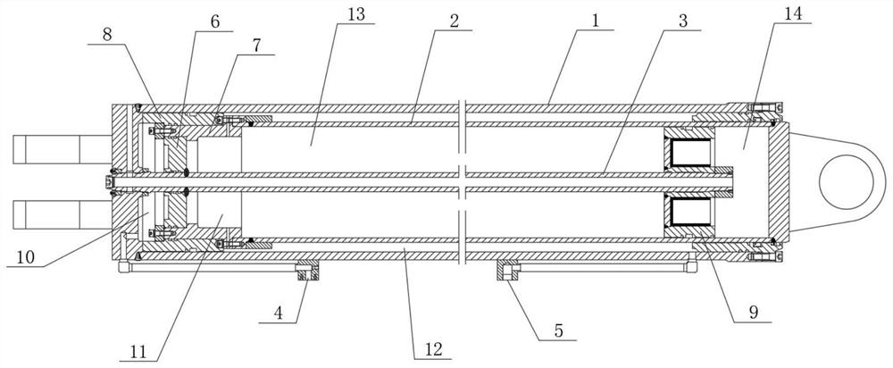
[0030] like figure 1 As shown, a piston rod cavity oil storage cylinder includes a cylinder body 1, a first piston rod 2 arranged in the cylinder body, a second piston rod 3 arranged in the first piston rod, and a The first oil inlet 4 on the cylinder block and the second oil inlet 5 provided on the cylinder block.

[0031] The bottom end of the second piston rod is provided with a guide sleeve 6, and the peripheral side wa...


PUM


Abstract

The invention discloses a piston rod cavity oil storage oil cylinder which comprises a cylinder body, a first piston rod arranged in the cylinder body, a second piston rod arranged in the first piston rod, a first oil inlet formed in the cylinder body and a second oil inlet formed in the cylinder body. A guide sleeve is arranged at the bottom end of the second piston rod, and a rod plug is arranged on the peripheral side wall of the guide sleeve; a first piston is arranged at the bottom of the cylinder body, the rod plug is tightly attached to the inner wall of the cylinder body, and the first piston rod abuts against the upper edge of the rod plug. A second piston is arranged at the head end of the second piston rod, and the bottom end of the second piston rod penetrates through the center of the guide sleeve and is arranged in the center of the end of the cylinder body. The guide sleeve is arranged at the bottom end of the second piston rod, and the rod plug is arranged on the peripheral side wall of the guide sleeve, so that the purposes of optimizing the whole oil cylinder structure, being convenient to disassemble, reducing friction between the piston and the cylinder barrel and improving the use quality of the oil cylinder are achieved.

Description

technical field [0001] The invention relates to the field of production and manufacture of oil cylinders, in particular to a piston rod cavity oil storage oil cylinder. Background technique [0002] In the prior art, a hydraulic cylinder is a hydraulic actuator that converts hydraulic energy into mechanical energy and performs linear reciprocating motion (or swing motion). It has simple structure and reliable operation. When using it to achieve reciprocating motion, the reduction device can be omitted, and there is no transmission gap, and the movement is stable, so it is widely used in various mechanical hydraulic systems. In the traditional hydraulic cylinder, the welding deformation area of ​​the rod plug at the outer piston rod extends to the piston part after the cylinder is fully extended, resulting in increased friction and affecting the quality of the cylinder. [0003] The information disclosed in this Background section is only for enhancement of understanding of...

Claims


Application Information

Patent Timeline
IPC IPC(8): F15B15/14F15B15/20
CPCF15B15/1423F15B15/1471F15B15/1457F15B15/1447F15B2215/30
Inventor 张民王启重夏继伟谢峰刘震蔺波
Owner XUZHOU YANHUANG ENG MACHINERY
Why Eureka
Try Eureka