
Corrugated pipe ball valve

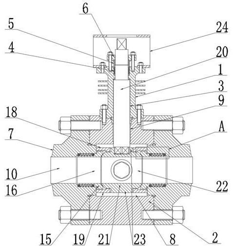
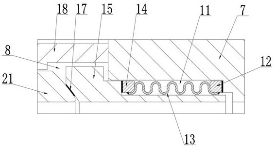
A bellows and ball valve technology, applied in the field of bellows ball valves, can solve the problems of ball valve sealing leakage, complicated operation and high difficulty, and achieve the effects of ensuring stability, simple overall structure, and easy maintenance and maintenance.

Pending Publication Date: 2022-07-01
纳福希(上海)阀门科技有限公司
View PDF0 Cites 0 Cited by
  • Summary
  • Abstract
  • Description
  • Claims
  • Application Information

AI Technical Summary

Problems solved by technology

[0002] The bellows of the two-way bellows ball valve in the coking unit are respectively connected to the valve seat and the valve cover in a welded form. During maintenance and replacement, they need to be cut off to replace the valve seat or bellows, which is difficult and complicated to operate. In the case of low temperature, it is easy to cause the problem of seal leakage, and in the case of extremely high temperature, it is easy to cause the problem of locking. Therefore, an improved technology is urgently needed to solve this problem in the prior art

Method used


Image

  • Corrugated pipe ball valve
  • Corrugated pipe ball valve
  • Corrugated pipe ball valve

Examples


Embodiment Construction

[0028] The technical solutions of the present invention will be clearly and completely described below with reference to the accompanying drawings in the embodiments of the present invention. Obviously, the described embodiments are only a part of the embodiments of the present invention, not all of the embodiments. Based on the embodiments of the present invention, all other embodiments obtained by those of ordinary skill in the art without creative work fall within the protection scope of the present invention;

[0029] It should be noted that, in the description of the present invention, it should be noted that the terms "inner", "outer", "upper", "lower", "both sides", "one end", "the other end" and "left" The orientation or positional relationship indicated by "right" and the like is based on the orientation or positional relationship shown in the drawings, and is only for the convenience of describing the present invention and simplifying the description, rather than indi...


PUM


Abstract

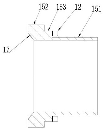
The bottom end of a valve body is connected with the upper surface of a valve seat, end covers are arranged at the two ends of the valve seat, assembling grooves are formed in the inner sides of the end covers, first connecting rings are arranged in the assembling grooves formed in the inner sides of the end covers, and the first connecting rings and one end of a corrugated pipe are matched and connected in an inserted mode; the other end of the corrugated pipe is matched with and connected with a second connecting ring in an inserted mode, the second connecting ring is connected with a sleeve pressing ring, a gap is reserved between the sleeve pressing ring and the inner wall of an assembling groove formed in the end cover, an upper half sealing ring and a lower half sealing ring are further arranged on the inner side of the end cover, and the ball valve is arranged in a cavity in the valve seat. Under the condition of low temperature or high temperature, the position of the sleeve pressing ring is changed through the corrugated pipe, so that sealing between the sleeve pressing ring and the ball valve is kept all the time, the application range is greatly widened, cutting is not needed when the corrugated pipe is maintained, the corrugated pipe is convenient to replace, and a gap is reserved between the sleeve pressing ring and the inner wall of the assembling groove formed in the end cover. And the condition of locking during thermal expansion is prevented.

Description

technical field [0001] The invention relates to the technical field of ball valves, in particular to a bellows ball valve. Background technique [0002] The bellows of the two-way bellows ball valve in the coking unit are respectively connected with the valve seat and the valve cover in the form of welding. During maintenance and replacement, the valve seat or bellows should be cut off to replace the valve seat or bellows, which is difficult and complicated to operate. In the case of low temperature, it is easy to cause the problem of seal leakage, and in the case of extremely high temperature, the problem of locking is easy to occur. Therefore, an improved technology is urgently needed to solve this problem in the prior art. SUMMARY OF THE INVENTION [0003] The purpose of the present invention is to provide a bellows ball valve, the bellows is arranged in the assembly groove of the end cover through the first connecting ring, and the sleeve pressing ring is connected wit...

Claims


Application Information

Patent Timeline
Patent Type & Authority Applications(China)
IPC IPC(8): F16K5/20F16K5/06F16K27/06F16K27/08F16K41/02
CPCF16K5/201F16K5/0647F16K5/0689F16K5/0694F16K27/067F16K27/08
Inventor 辛朋洲
Owner 纳福希(上海)阀门科技有限公司
Learn More