Power energy assembly, power energy assembly assembling method and vehicle

A technology for power energy and assembly assembly, applied in electric vehicles, vehicle components, vehicle energy storage, etc., can solve problems such as hydrogen leakage, lack of protective measures for hydrogen storage tanks, and increase the complexity of vehicle assembly operations, so as to improve the collision rate. safety effect

Pending Publication Date: 2022-07-01
FTXT ENERGY TECH CO LTD
View PDF0 Cites 0 Cited by
  • Summary
  • Abstract
  • Description
  • Claims
  • Application Information

AI Technical Summary

Problems solved by technology

Due to the scattered layout of the components of the fuel cell system, the complexity of the vehicle assembly operation is increased
In addition, the hydrogen storage tank is used to store hydrogen, and there is a risk of hydrogen leakage and explosion when the vehicle is hit by a collision. In the past, the protection measures for the hydrogen storage tank were lacking in the overall layout of the fuel cell system

Method used


Image

  • Power energy assembly, power energy assembly assembling method and vehicle
  • Power energy assembly, power energy assembly assembling method and vehicle
  • Power energy assembly, power energy assembly assembling method and vehicle

Examples


Embodiment 1

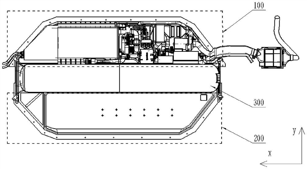
[0033] like figure 1 and figure 2 As shown, the power energy assembly provided by the embodiment of the present invention includes: a fuel cell system 100, a power battery system 200, and a hydrogen storage system 300;

[0034] The fuel cell system 100 and the power cell system 200 are arranged at intervals, and an installation area is formed between the fuel cell system 100 and the power cell system 200;

[0035] The hydrogen storage system 300 is installed in the installation area.

[0036] Specifically, the fuel cell system 100 and the power battery system 200 are figure 1 The central y-axis direction is spaced apart, and the hydrogen storage system 300 is installed between the fuel cell system 100 and the power battery system 200. The fuel cell system 100 and the power battery system 200 play a protective role for the hydrogen storage system 300, thereby reducing the risk of damage from the y-axis. The impact force in the direction improves the collision safety of the ...

Embodiment 2

[0051] like figure 1 , figure 2 , image 3 , Figure 4 and Figure 5 As shown, the power source assembly assembly method provided by the embodiment of the present invention includes:

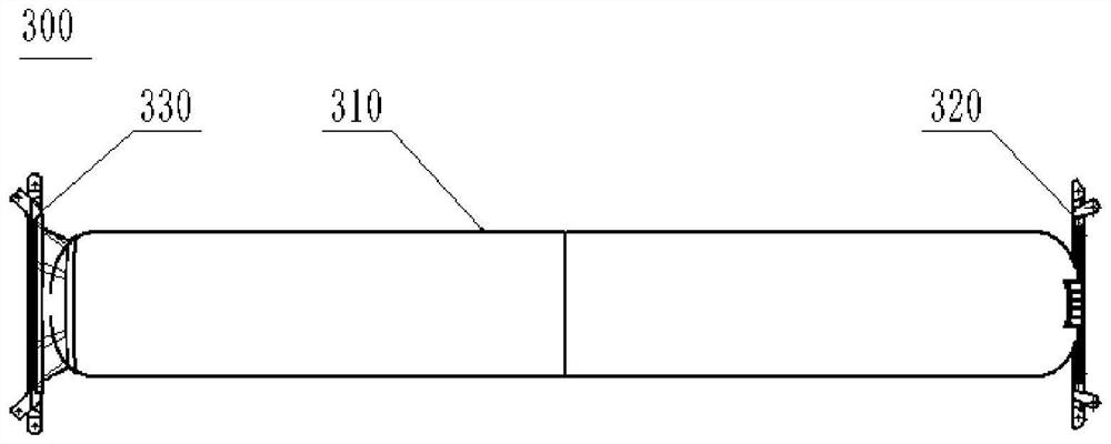
[0052] The hydrogen storage system 300 is installed between the fuel cell system 100 and the power battery system 200 .

[0053] Specifically, the hydrogen storage system 300 is located between the fuel cell system 100 and the power battery system 200. When either of the fuel cell system 100 and the power battery system 200 is collided, the impact of the collision on the hydrogen storage system 300 can be mitigated , thereby improving the safety of the hydrogen storage system 300 in a collision.

[0054] In the embodiment of the present invention, the steps of installing the hydrogen storage system 300 between the fuel cell system 100 and the power battery system 200 include:

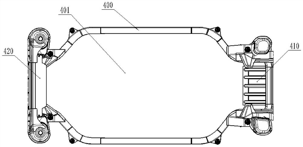
[0055] along the first direction, the hydrogen storage system 300 is installed in the accommodating space 401 su...

Embodiment 3

[0059] like figure 1 , figure 2 , image 3 , Figure 4 and Figure 5 As shown, the vehicle provided by the embodiment of the present invention is provided with the power energy assembly provided by the first embodiment.

[0060] The vehicle provided in this embodiment has the technical effect of the above-mentioned fuel cell system, which is not repeated here.

[0061] It should be noted that, along the traveling direction of the vehicle, both ends of the hydrogen storage system 300 are respectively connected to the chassis frame. Wherein, the protective frame 400 can be configured as a chassis frame, or the protective frame 400 can be used as a component of the chassis frame. When the vehicle is subjected to a frontal collision, the hydrogen storage system 300 can participate in the transmission of force, thereby improving the rigidity of the vehicle.

[0062] In addition, taking the traveling direction of the vehicle as the front view direction, one of the fuel cell sy...


PUM


Abstract

The invention provides a power energy assembly, a power energy assembly assembling method and a vehicle, and relates to the technical field of vehicle-mounted fuel cell, the power energy assembly provided by the invention comprises a fuel cell system, a power cell system and a hydrogen storage system; the fuel cell system and the power cell system are arranged at an interval, and a mounting area is formed between the fuel cell system and the power cell system; and the hydrogen storage system is mounted in the mounting area. According to the power energy assembly provided by the invention, integrated installation of the fuel cell system, the power cell system and the hydrogen storage system is realized, so that scattered arrangement of each component is avoided, the hydrogen storage system is protected through the fuel cell system and the power cell system, and the collision safety of the hydrogen storage system is improved.

Description

technical field [0001] The invention relates to the technical field of vehicle fuel cells, in particular to a power energy assembly, a power energy assembly assembly method and a vehicle. Background technique [0002] When the on-board fuel cell system is equipped, the stack is usually installed under the cabin or the middle floor, and the power battery system and hydrogen storage tank are installed in the rear floor or trunk. Due to the scattered arrangement of various components of the fuel cell system, the complexity of the vehicle assembly operation is increased. In addition, the hydrogen storage tank is used to store hydrogen, and there is a risk of hydrogen leakage and explosion when the vehicle is hit by a collision. In the past, when the fuel cell system was arranged as a whole, the protective measures for the hydrogen storage tank were lacking. SUMMARY OF THE INVENTION [0003] The purpose of the present invention is to provide a power energy assembly, a power en...

Claims


Application Information

Patent Timeline
IPC IPC(8): H01M16/00H01M8/04082H01M50/249H01M50/258H01M50/244H01M50/289B60L50/64
CPCH01M16/00H01M8/04201B60L50/64Y02T10/70
Inventor 李新乐原强杨泽臣
Owner FTXT ENERGY TECH CO LTD
Why Eureka
Try Eureka