Smoke dust treatment device for large casting equipment and use method of smoke dust treatment device

A casting equipment and processing device technology, which is applied in the field of smoke and dust processing devices for large casting equipment, can solve the problems of inconvenient dust cleaning, easy to affect the normal exhaust of exhaust pipes, etc., and achieve the effect of increasing sealing

Pending Publication Date: 2022-07-05
芜湖久弘重工股份有限公司
View PDF0 Cites 1 Cited by
  • Summary
  • Abstract
  • Description
  • Claims
  • Application Information

AI Technical Summary

Problems solved by technology

[0004] The purpose of the present invention is to solve the disadvantages in the prior art that the traditional smoke treatment device is inconvenient to clean the filtered dust on the premise that it can filter the smoke, and the accumulation of dust in the exhaust pipe will easily affect the normal exhaust of the exhaust pipe. A proposed fume treatment device for large foundry equipment and its application method

Method used


Image

  • Smoke dust treatment device for large casting equipment and use method of smoke dust treatment device
  • Smoke dust treatment device for large casting equipment and use method of smoke dust treatment device
  • Smoke dust treatment device for large casting equipment and use method of smoke dust treatment device

Examples


Embodiment 1

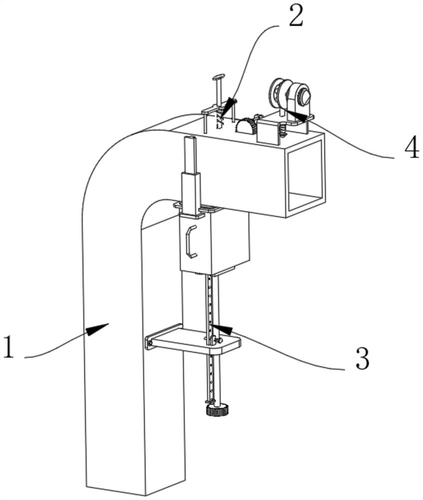
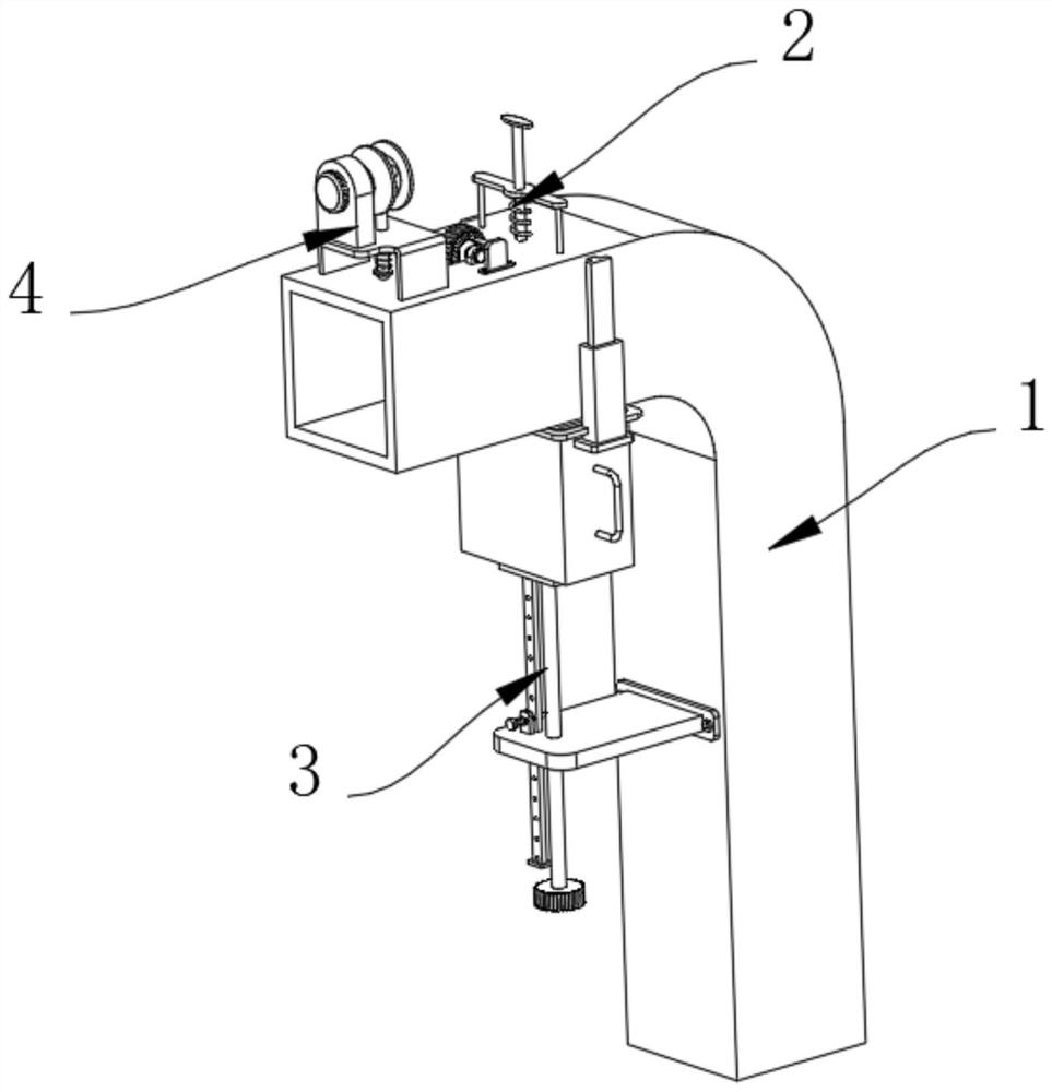
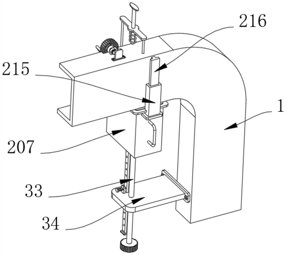
[0047] Example 1, as Figure 1-8 As shown, the present invention provides a fume treatment device for large-scale foundry equipment and a method of using the same, comprising a fume exhaust pipe 1, a support structure 3 and a filter structure 2, and the upper surface of the short arm end of the exhaust pipe 1 is provided with a filter structure 2 , the lower end of the collection box 207 is provided with a support structure 3 , and the upper surface of the short arm end of the smoke exhaust pipe 1 is provided with an auxiliary structure 4 .

[0048] The specific settings and functions of the filter structure 2 , the support structure 3 and the auxiliary structure 4 will be described in detail below.

[0049] like image 3 and Figure 4 As shown, the filter structure 2 includes a motor 201, the motor 201 is fixedly connected to the surface of the smoke exhaust pipe 1, the output end of the motor 201 is fixedly connected with a gear A202, the smoke exhaust pipe 1 is provided w...

Embodiment 2

[0053] Embodiment 2, on the basis of embodiment 1, as Figure 7 and Figure 8As shown, the auxiliary structure 4 includes a fixing frame 41, the fixing frame 41 is fixedly connected to the surface of the smoke exhaust pipe 1, a top rod 42 is slidably inserted in the fixed frame 41, and the lower end of the top rod 42 is fixedly connected to be used for knocking the smoke exhaust pipe 1, the circular arc surface of the ejector rod 42 is covered with a spring C44, the two ends of the spring C44 are respectively fixedly connected with the ejector rod 42 and the tapping block 43, and the upper surface of the fixing frame 41 is fixedly connected with a mounting block 45, The mounting block 45 is fixedly connected with a motor 46 for driving, and the output end of the motor 46 is fixedly connected with an adjusting member 47 for adjusting the reciprocating motion of the ejector rod 42, so that the position of the ejector rod 42 can be quickly adjusted by means of the adjusting membe...


PUM


Abstract

The invention provides a smoke dust treatment device for large casting equipment and a using method thereof, and relates to the technical field of smoke dust treatment devices.The smoke dust treatment device comprises a smoke exhaust pipe, a supporting structure and a filtering structure, the filtering structure is arranged on the upper surface of the short arm end of the smoke exhaust pipe and comprises a motor, and the motor is fixedly connected to the surface of the smoke exhaust pipe; the output end of the motor is fixedly connected with a gear A. A reserved hole is formed in the position, corresponding to the gear A, of the smoke exhaust pipe. The tooth surface of the gear A is meshed with a gear B. The two sides of the gear B are fixedly connected with filter plates used for filtering dust in waste gas, and the two sides of each filter plate are rotationally connected with the smoke exhaust pipe. The side, close to the motor, of the smoke exhaust pipe is fixedly connected with a fixing plate. According to the smoke dust treatment device, the problems that filtered dust is inconvenient to clean in time on the premise that a traditional smoke dust treatment device can filter smoke dust, and normal exhaust of the waste gas pipe is easily affected due to accumulation of the dust in the waste gas pipe are solved.

Description

technical field [0001] The invention relates to the technical field of fume treatment devices, in particular to a fume treatment device for large-scale foundry equipment and a method for using the same. Background technique [0002] The soot treatment device refers to a device that filters and purifies the soot in the exhaust gas. With the advancement of the process of energy saving and environmental protection, it is widely used in large foundries. With the development of the times, the filter of the soot treatment device methods are gradually increasing. [0003] When large-scale casting equipment casts the workpiece, it will generate a certain amount of smoke and dust. The smoke and dust are mixed with air and discharged from the exhaust pipe. Generally, a smoke and dust treatment device is installed inside the exhaust pipe. The traditional smoke and dust treatment device is inconvenient under the premise of being able to filter the smoke and dust. Clean the filtered dus...

Claims


Application Information

Patent Timeline
IPC IPC(8): B01D46/10B01D46/48B01D46/681B08B15/04B08B9/027B08B7/02B22D45/00
CPCB01D46/10B01D46/48B08B15/04B08B9/027B08B7/02B22D45/005B08B2209/027
Inventor 何文东艾明姬唱
Owner 芜湖久弘重工股份有限公司
Why Eureka
Try Eureka