Pantograph device and electric vehicle

A technology of pantograph and charging bow, which is applied in the field of electric locomotive power supply equipment, can solve the problems of lower reliability and lower reliability of pantograph, and achieve the effect of improving reliability

Pending Publication Date: 2022-07-05
QINGDAO TELD NEW ENERGY TECH CO LTD
View PDF0 Cites 0 Cited by
  • Summary
  • Abstract
  • Description
  • Claims
  • Application Information

AI Technical Summary

Problems solved by technology

[0002] The pantograph is a current-receiving device for large-scale electric vehicles to receive current from the charging bow. Since the multiple electrodes of the pantograph are usually installed on the roof of the electric vehicle through insulators, the electrodes of the pantograph may be damaged by foreign objects. problems that reduce reliability due to touch
[0003] To this end, the related art provides a pantograph device with a cover, the cover is installed on the top of the electric vehicle, and the cover is provided with a plurality of openings corresponding to a plurality of electrodes, each electrode can pass through The corresponding opening protrudes to the outside of the cover so that the electrodes of the pantograph can be docked with the electrodes of the charging bow. However, such an arrangement makes it easy to form a water-conducting film on the surface of the cover of the pantograph in rainy days, so that the copper bars It is easy to conduct with the cover body, so that the surface of multiple copper bars of the pantograph is easily conducted, which reduces the reliability of the pantograph

Method used


Image

  • Pantograph device and electric vehicle
  • Pantograph device and electric vehicle
  • Pantograph device and electric vehicle

Examples


Embodiment Construction

[0036] In view of this, the core of the present invention is to provide a pantograph device, when the pantograph device is wet in rainy or snowy days, etc., the pantograph device can avoid the conduction between the copper bar and the cover body and the multiple copper bars. The surfaces are conductive with each other, thereby effectively improving the reliability of the pantograph device.

[0037] Another core of the present invention is to provide an electric vehicle.

[0038] In order to make those skilled in the art better understand the solution of the present invention, the present invention will be further described in detail below with reference to the accompanying drawings and specific embodiments.

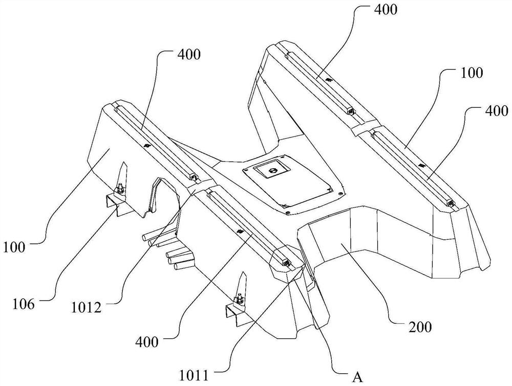
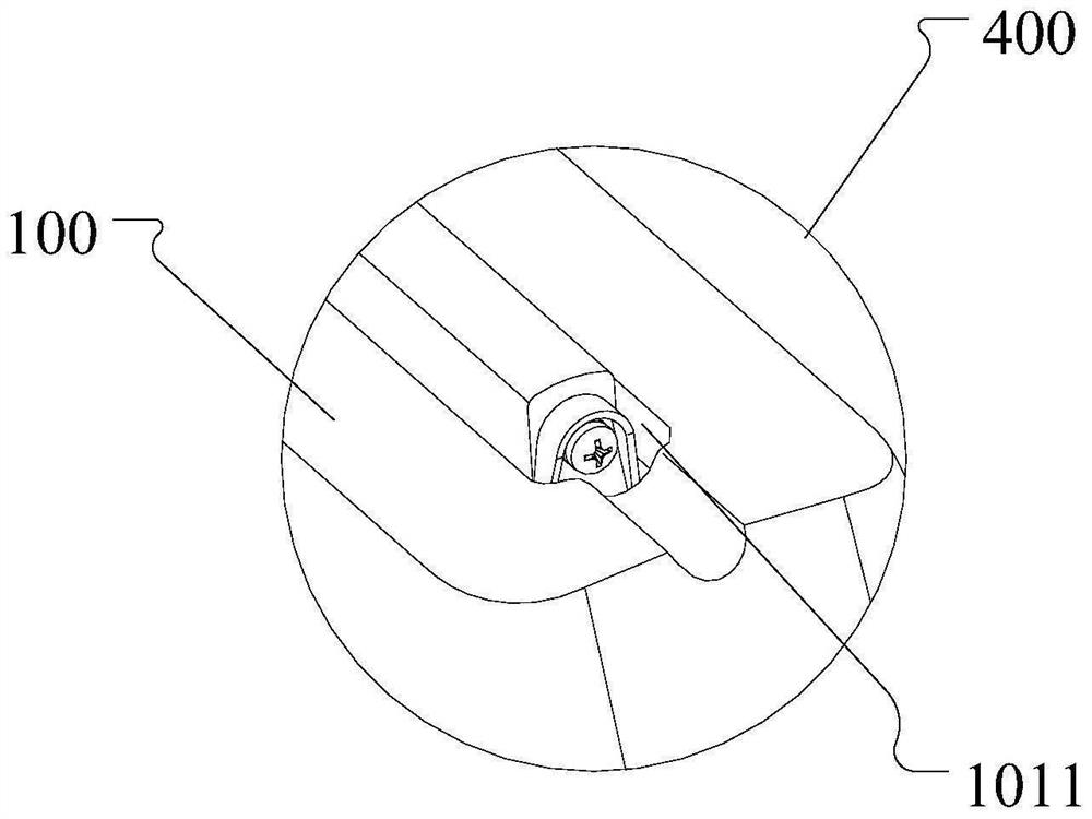
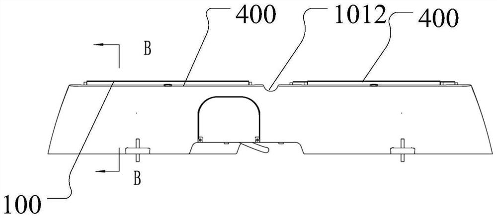
[0039] Please refer to Figure 1 to Figure 5 , The pantograph device disclosed in the embodiment of the present invention includes a cover body, an insulating support 300 and at least two copper bars 400 arranged at intervals. The copper bars 400 are arranged on the copp...


PUM


Abstract

The pantograph device comprises a cover body, an insulation support and at least two copper bars arranged at intervals, the copper bars are arranged on a copper bar installation part of the insulation support, the cover body covers the insulation support and the copper bars, the cover body is provided with an opening for the copper bars to stretch out, and the copper bars are arranged in the opening. The edge of the opening, the copper bar and the insulating support are arranged at intervals, and the contact face, used for being in lap joint with the charging bow device, of the copper bar extends out of the outer side of the cover body through the opening so that the copper bar can make contact with the charging bow device. The cover body comprises a first mounting part and a second mounting part which are arranged in the cover body, are connected with the insulating bracket and are respectively positioned on two sides of the opening; the insulation support comprises a third installation part connected with the first installation part and a fourth installation part connected with the second installation part, the third installation part and the fourth installation part are both configured to be located outside a water flow path entering from the opening, the structure can avoid conduction between the copper bar and the cover body, and the reliability of the pantograph device is improved.

Description

technical field [0001] The invention relates to the technical field of power supply equipment for electric locomotives, in particular to a pantograph device and an electric vehicle. Background technique [0002] The pantograph is a current receiving device for large electric vehicles to receive current from the charging bow. Since the multiple electrodes of the pantograph are usually installed on the roof of the electric vehicle through insulators, the electrodes of the pantograph may be touched by foreign objects. The problem of reduced reliability due to contact. [0003] To this end, the related art provides a pantograph device with a cover body, the cover body is mounted on the top of an electric vehicle, and the cover body is provided with a plurality of openings corresponding to a plurality of electrodes, and each electrode can pass through The corresponding openings extend to the outside of the cover, so that the electrodes of the pantograph can be connected to the e...

Claims


Application Information

Patent Timeline
IPC IPC(8): B60L5/18B60L5/20
CPCB60L5/18B60L5/20Y02T90/14
Inventor 宋业北夏修龙闫丽霞
Owner QINGDAO TELD NEW ENERGY TECH CO LTD
Why Eureka
Try Eureka