Valve system capable of being quickly opened and closed

A fast and valve technology, applied to valve details, valve devices, sliding valves, etc., can solve problems such as liquid or gas leakage, poor sealing, inconvenient operation, etc., to achieve rapid opening or closing, improve timeliness, and avoid accidental contact.

Pending Publication Date: 2022-07-05
SHOUGANG SHUICHENG IRON & STEEL GRP
View PDF0 Cites 0 Cited by
  • Summary
  • Abstract
  • Description
  • Claims
  • Application Information

AI Technical Summary

Problems solved by technology

[0002] Valves are pipeline accessories used to open and close pipelines, control flow direction, adjust and control the parameters (temperature, pressure and flow) of the conveying medium. According to their functions, they can be divided into shut-off valves, check valves, regulating valves, etc. Valves can be used to control the flow of various types of fluids such as air, water, steam, various corrosive media, mud, oil, liquid metal and radioactive media. However, due to long-term use of existing valves, when the valve is opened, There will be a gap between the screw rod of the control valve and the center line of the valve, which will cause liquid or gas to leak, resulting in poor sealing. At the same time, there are problems of low practicability and inconvenient operation of the existing valves.
[0003] In the prior art, the valve is generally opened or closed by rotating the handwheel, which makes it extremely inconvenient to close or open the valve, and cannot be opened or closed quickly

Method used


Image

  • Valve system capable of being quickly opened and closed
  • Valve system capable of being quickly opened and closed
  • Valve system capable of being quickly opened and closed

Examples


Embodiment Construction

[0018] The technical solutions in the embodiments of the present invention will be clearly and completely described below with reference to the accompanying drawings. Obviously, the described embodiments are only a part of the embodiments of the present invention, rather than all the embodiments.

[0019] In the description of the present invention, it should be understood that the terms "upper", "lower", "front", "rear", "left", "right", "top", "bottom", "inside", " The orientation or positional relationship indicated by "outside" is based on the orientation or positional relationship shown in the accompanying drawings, and is only for the convenience of describing the present invention and simplifying the description, rather than indicating or implying that the indicated device or element must have a specific orientation, so as to The specific orientation configuration and operation are therefore not to be construed as limitations of the present invention.
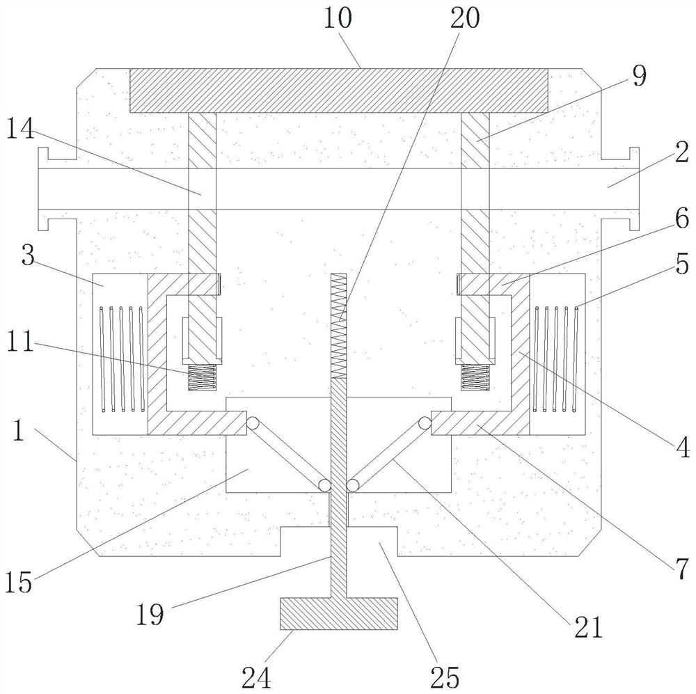
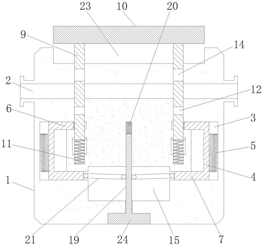
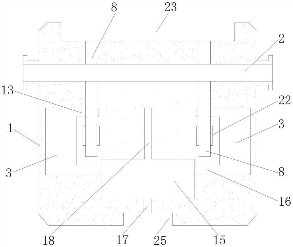
[0020] see attac...


PUM


Abstract

A valve system capable of being rapidly opened and closed comprises a shell, a fluid channel is formed in the shell, sliding grooves are symmetrically formed in the lower end of the fluid channel, locking blocks slide in the sliding grooves, first springs are arranged between the locking blocks and the bottoms of the sliding grooves, the upper portions and the lower portions of the close ends of the two locking blocks are connected with locking rods respectively, and valve grooves are symmetrically formed in the shell in the vertical direction; the valve groove is slidably connected with a valve plate, the valve plate penetrates through the fluid channel to extend into the valve groove to be connected with a second spring, a lock hole is formed in the valve plate, first through holes are formed in the upper ends of the close sides of the two sliding grooves, the lock rod penetrates through the first through holes to be clamped in the lock hole, a valve port is formed in the valve plate, a cavity is formed in the shell, and second through holes are formed in the lower ends of the close sides of the two sliding grooves. A guide hole communicated with the outside of the shell is formed in the cavity, a guide rod is slidably connected to the guide hole, rotating rods are symmetrically and rotatably connected to the guide rod in the cavity, and the lock rod penetrates through the second through hole to be connected with the other ends of the rotating rods. The valve can be quickly opened or closed and locked, and mistaken touch is avoided.

Description

technical field [0001] The invention relates to the technical field of valve equipment, in particular to a valve system that can be opened and closed quickly. Background technique [0002] The valve is a pipeline accessory used to open and close the pipeline, control the flow direction, and adjust and control the parameters (temperature, pressure and flow) of the conveying medium. According to its function, it can be divided into shut-off valve, check valve, regulating valve, etc. The valve can be used to control the flow of various types of fluids such as air, water, steam, various corrosive media, mud, oil, liquid metal and radioactive media, but the existing valve due to long-term use, when the valve is opened, There will be a gap between the screw rod of the control valve and the center line of the valve, which will cause liquid or gas leakage, resulting in poor sealing. [0003] In the prior art, the valve is generally opened or closed by rotating the handwheel, which ...

Claims


Application Information

Patent Timeline
Patent Type & Authority Applications(China)
IPC IPC(8): F16K3/02F16K31/56F16K35/02F16K35/10
CPCF16K3/0254F16K3/029F16K35/027F16K35/10F16K31/56
Inventor 熊波聂宗琦付钢王国祚谢智玲吴俊王明忠
Owner SHOUGANG SHUICHENG IRON & STEEL GRP
Why Eureka
Try Eureka