
Battery automatic OCV test device

A technology for testing equipment and batteries, applied in the parts of electrical measuring instruments, measuring electricity, measuring devices, etc., can solve the problems of battery short circuit, battery fire, safety threats to operators, etc., to maintain stable operation and improve safety. Effect

Pending Publication Date: 2022-07-05
东莞市爱康智能技术有限公司
View PDF0 Cites 0 Cited by
  • Summary
  • Abstract
  • Description
  • Claims
  • Application Information

AI Technical Summary

Problems solved by technology

[0002] In the production process of the battery, the finished battery needs to go through the final inspection process to check whether the parameters such as voltage, current, and resistance of the battery are within the acceptable range before they can be packaged and sold. When measuring the parameters of the battery, the measured The probes on the device are connected to the positive and negative ears of the battery respectively, and then the battery is energized for detection. However, during the detection process, some unqualified batteries will short-circuit after power-on, and even cause the battery to catch fire. Currently The detection equipment is not equipped with a fire extinguishing mechanism to deal with the battery fire, and the fire battery can only be carried out of the equipment manually, and then the fire is extinguished. Not only is the fire extinguishing efficiency low, but it also poses a threat to the safety of the operator. Therefore, It is necessary to make a battery automatic OCV test equipment, which can safely and quickly put out the fire of the battery to solve the above problems

Method used


Image

  • Battery automatic OCV test device
  • Battery automatic OCV test device
  • Battery automatic OCV test device

Examples


Embodiment Construction

[0034] The present invention will be further described below in conjunction with the accompanying drawings:

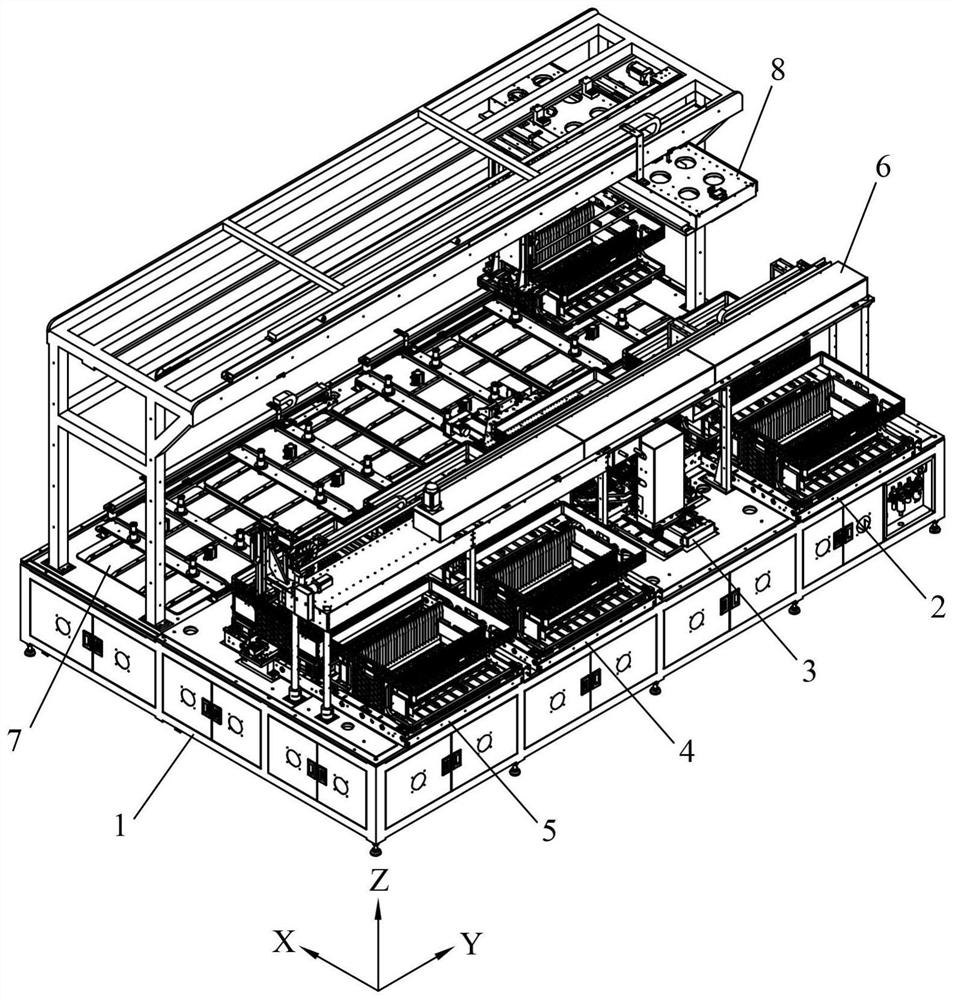
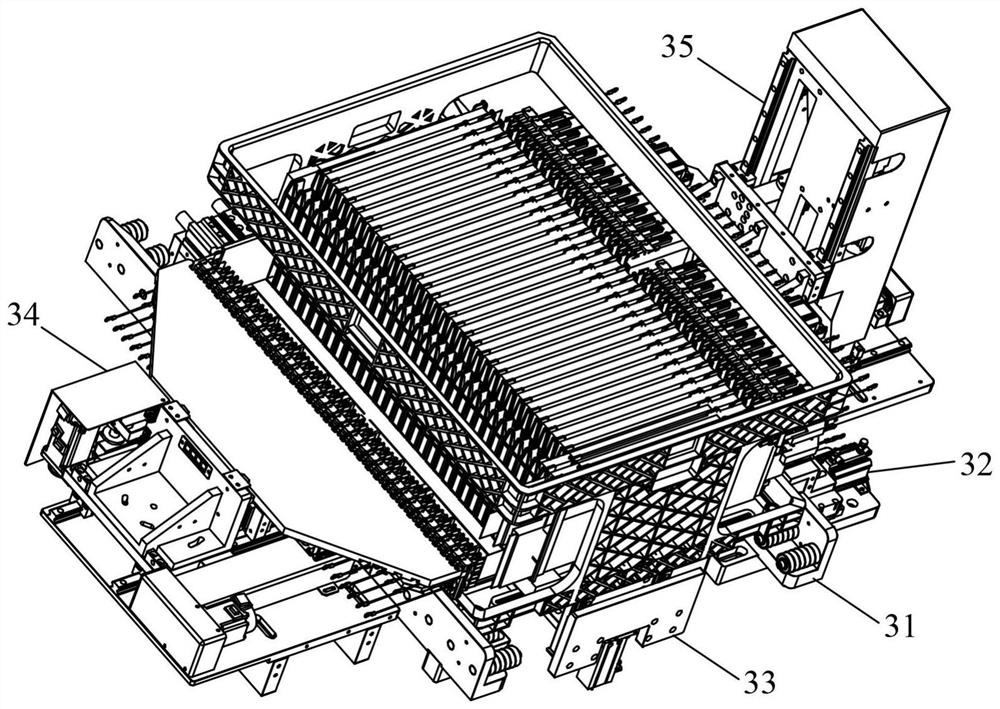
[0035] like figure 1 As shown, an automatic battery OCV testing equipment includes a rack 1, a feeding and conveying mechanism 2, a battery measuring mechanism 3, a discharging and conveying mechanism 4, a NG buffer mechanism 5, a handling manipulator 6, a battery fire extinguishing mechanism 7, and a material frame handling mechanism. The mechanism 8 and the smoke sensor, the feeding conveying mechanism 2, the battery measuring mechanism 3, the unloading conveying mechanism 4 and the NG buffer mechanism 5 are sequentially fixed on the right side of the rack 1, and the handling manipulator 6 is erected on the right side above the rack 1, The battery fire extinguishing mechanism 7 is fixed on the left side of the frame 1, and the material frame conveying mechanism 8 is erected on the left side above the frame 1. The smoke sensor is fixed on the frame 1. There are multip...


PUM


Abstract

The invention provides automatic battery OCV testing equipment which comprises a rack, a feeding conveying mechanism, a battery measuring mechanism, a discharging conveying mechanism, an NG caching mechanism, a carrying mechanical arm, a battery fire extinguishing mechanism, a material frame carrying mechanism and a smoke sensor, and the feeding conveying mechanism, the battery measuring mechanism, the discharging conveying mechanism and the NG caching mechanism are sequentially fixed to the right side of the rack; the carrying manipulator is erected on the right side of the upper portion of the rack, the battery fire extinguishing mechanism is fixed to the left side of the rack, the material frame carrying mechanism is erected on the left side of the upper portion of the rack, the smoke sensors are fixed to the rack, and the multiple sets of smoke sensors are arranged above the feeding conveying mechanism, the battery measuring mechanism, the discharging conveying mechanism and the NG caching mechanism correspondingly. The fire extinguishing device has the advantages that the fire catching phenomenon of the battery can be found in time, the fire behavior can be extinguished automatically and efficiently, on one hand, stable operation of equipment can be maintained, and on the other hand, the safety of the equipment is also improved.

Description

technical field [0001] The invention relates to the field of battery processing equipment, in particular to an automatic battery OCV testing device. Background technique [0002] In the production process of the battery, the battery after the production needs to go through the last testing process to check whether the parameters such as voltage, current and resistance of the battery are within the qualified range before packaging and selling. When measuring the parameters of the battery, the measurement The probe on the device is connected to the positive and negative terminals of the battery, and then the battery is powered on for testing. However, during the testing process, some unqualified batteries will short-circuit after power-on, and even cause the battery to catch fire. The detection equipment is not equipped with a fire extinguishing mechanism to deal with the situation of the battery on fire. Only by manually transporting the burning battery to the outside of the ...

Claims


Application Information

Patent Timeline
Patent Type & Authority Applications(China)
IPC IPC(8): G01R31/36G01R31/389G01R1/02B65G47/90
CPCG01R31/36G01R31/389G01R1/02B65G47/901
Inventor 陈运锋袁楚辉吴刚
Owner 东莞市爱康智能技术有限公司
Learn More