
Endogenous secure transmission state setting method of synchronous optical communication system and related equipment

A communication system and secure transmission technology, applied in the field of endogenous secure transmission state settings, to achieve the effects of improving security, reducing information theft, and enhancing effectiveness

Pending Publication Date: 2022-07-05
BEIJING UNIV OF POSTS & TELECOMM
View PDF0 Cites 0 Cited by
  • Summary
  • Abstract
  • Description
  • Claims
  • Application Information

AI Technical Summary

Problems solved by technology

[0002] Optical communication has the advantages of high speed, large capacity, and long-distance transmission. It is currently the most important means of communication. At present, in traditional "additional" optical communication, information may be "hijacked" at any time due to transparent transmission. Therefore, an additional key negotiation must be established between the sending and receiving parties to ensure the reliable transmission of information.
Once the outside world has mastered the key information, it can easily intercept the signal from any point of the transmission line and decrypt it to decipher the communication content. There is a shortcoming in the security of the physical layer of the optical network.

Method used


Image

  • Endogenous secure transmission state setting method of synchronous optical communication system and related equipment
  • Endogenous secure transmission state setting method of synchronous optical communication system and related equipment
  • Endogenous secure transmission state setting method of synchronous optical communication system and related equipment

Examples


Embodiment Construction

[0023] In order to make the objectives, technical solutions and advantages of the present application more clearly understood, the present application will be further described in detail below with reference to specific embodiments and accompanying drawings.

[0024] It should be noted that, unless otherwise defined, the technical terms or scientific terms used in the embodiments of the present application shall have the usual meanings understood by those with ordinary skills in the field to which the present application belongs. "First", "second" and similar words used in the embodiments of the present application do not indicate any order, quantity or importance, but are only used to distinguish different components. "Comprising" or "comprising" and similar words mean that the elements or things appearing before the word encompass the elements or things recited after the word and their equivalents, but do not exclude other elements or things. Words like "connected" or "conne...


PUM


Abstract

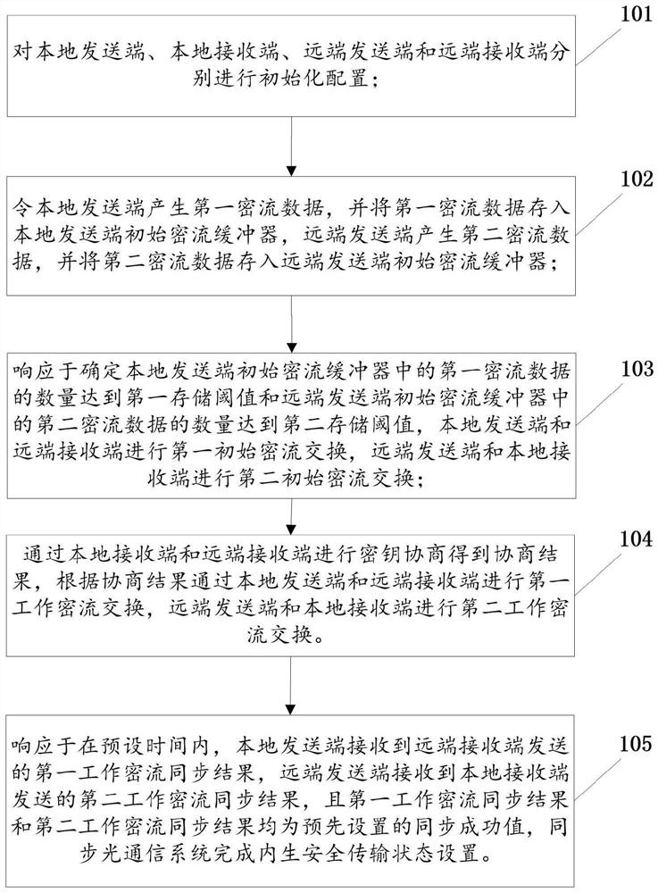
The invention provides an endogenous secure transmission state setting method of a synchronous optical communication system and related equipment, a local terminal comprises a local sending end and a local receiving end, and a far-end terminal comprises a far-end sending end and a far-end receiving end. The method comprises the following steps: a local sending end, a local receiving end, a far-end sending end and a far-end receiving end respectively carry out initialization configuration; the local sending end generates first dense flow data, and the far-end sending end generates second dense flow data; the local sending end and the far-end receiving end carry out first initial dense flow exchange, and the far-end sending end and the local receiving end carry out second initial dense flow exchange; the local receiving end and the remote receiving end carry out key negotiation to obtain a negotiation result, first working dense flow exchange is carried out through the local sending end and the remote receiving end according to the negotiation result, second working dense flow exchange is carried out through the remote sending end and the local receiving end, and the synchronous optical communication system completes endogenous secure transmission state setting. And the security in the optical communication transmission process is improved.

Description

technical field [0001] The present application relates to the technical field of optical communication, and in particular, to a method for setting an endogenous secure transmission state of a synchronous optical communication system and related equipment. Background technique [0002] Optical communication has the advantages of high speed, large capacity, long-distance transmission, etc., and is currently the most important means of communication. At present, in traditional "additional" optical communication, information is always "hijacked" due to transparent transmission. Therefore, an additional key agreement must be established between the sender and receiver to ensure the reliable transmission of information. Once the outside world has mastered the key information, it can easily intercept the signal from any point of the transmission line and decrypt it to decrypt the communication content. SUMMARY OF THE INVENTION [0003] In view of this, the purpose of the present...

Claims


Application Information

Patent Timeline
Patent Type & Authority Applications(China)
IPC IPC(8): H04L9/12H04L9/08
CPCH04L9/12H04L9/0838
Inventor 张会彬翟欢张雪影孙小惠张栋胜李欣
Owner BEIJING UNIV OF POSTS & TELECOMM
Learn More