
Intelligent laser-guided positioning sampling device for CT (computed tomography) puncture

A laser-guided and sampling device technology, applied in the direction of puncture needles, stereotaxic surgical instruments, surgical robots, etc., to achieve the effect of ensuring hygiene, reducing operating burden, and simple operation

Pending Publication Date: 2022-07-08
SICHUAN CANCER HOSPITAL
View PDF1 Cites 0 Cited by
  • Summary
  • Abstract
  • Description
  • Claims
  • Application Information

AI Technical Summary

Problems solved by technology

[0003] For example, a remote intelligent calibration laser positioning system based on X-ray image guidance disclosed in the invention with the authorized announcement number CN110180093A, although it can allow the system to judge the puncture point and puncture angle, it is not combined with CT puncture and cannot be controlled by the system. While judging the puncture location and angle, the system performs puncture sampling. For this reason, we propose a CT puncture intelligent laser-guided positioning sampling device.

Method used


Image

  • Intelligent laser-guided positioning sampling device for CT (computed tomography) puncture
  • Intelligent laser-guided positioning sampling device for CT (computed tomography) puncture
  • Intelligent laser-guided positioning sampling device for CT (computed tomography) puncture

Examples


Embodiment 1

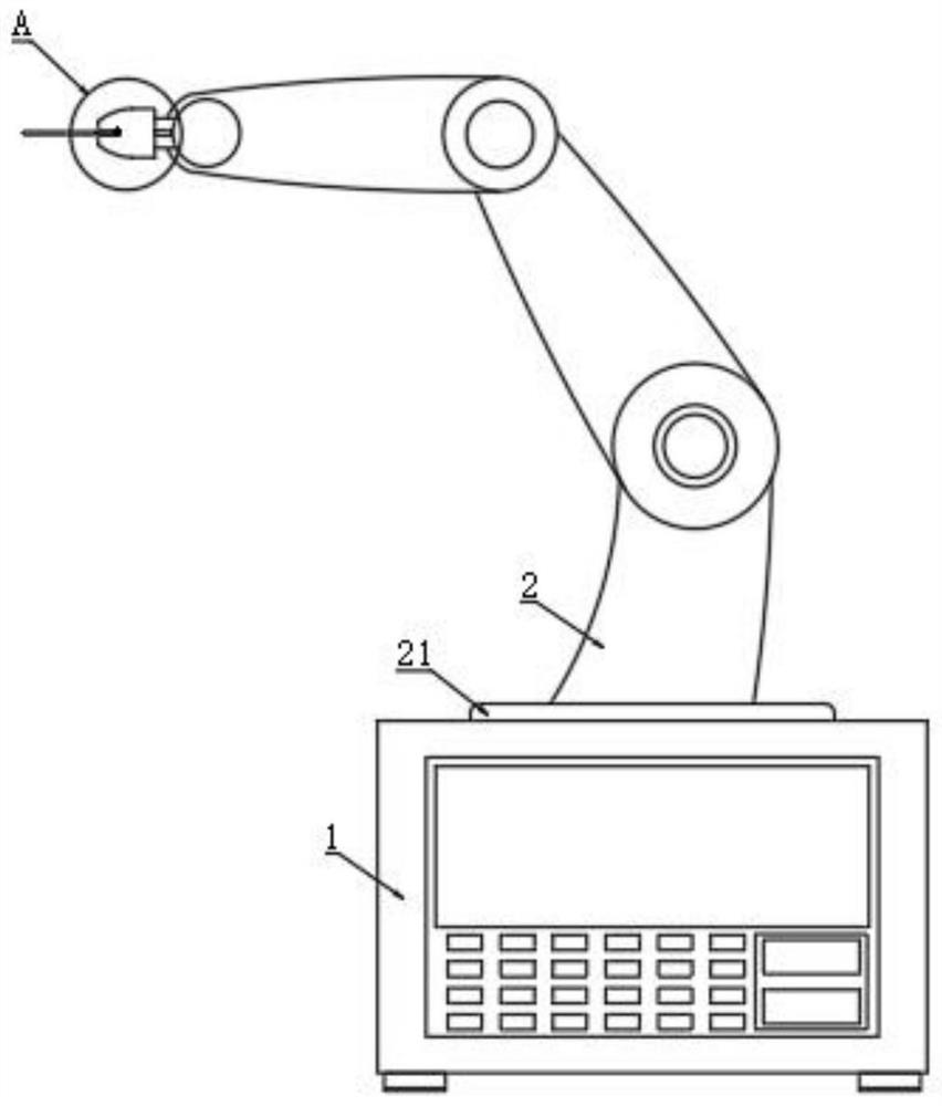
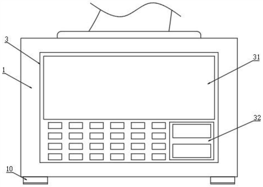
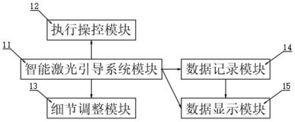
[0032] like Figure 1-Figure 4 As shown, the CT puncture intelligent laser-guided positioning sampling device includes a device body 1, a puncture mechanism and a control mechanism. The puncture mechanism includes a robotic arm 2, and the robotic arm 2 is located on the top surface of the device body 1; One end face of the robotic arm 2; a sliding rail 23, the sliding rail 23 is opened on the outside of the tip turning block 22; the sliding block 24, the sliding block 24 is slidably connected to the inner side of the sliding rail 23; the puncture needle 4, one end of the puncture needle 4 is movably connected to the sliding block 24 On the inner side, the other end of the puncture needle 4 is located outside the sliding block 24; the control mechanism includes the intelligent laser guidance system module 11, the execution control module 12, the detail adjustment module 13, the data recording module 14 and the data display module 15, the intelligent laser guidance system module ...

Embodiment 2

[0038] In other embodiments, this embodiment discloses, please such as figure 1 , Figure 4 , Figure 5 , Image 6 As shown, it also includes a connecting mechanism, the connecting mechanism includes a connecting groove 25, the connecting groove 25 is opened on one side surface of the sliding block 24, one end of the puncture needle 4 is movably connected to the inner side of the connecting groove 25, and the inner side of the connecting groove 25 is fixedly connected to the limiting block 26, A limit slot 41 is provided on the outside of the puncture needle 4, the limit block 26 is movably connected to the inner side of the limit slot 41, and four limit blocks 26 are arranged around the inner side of the connection slot 25. The limit slots 41 and the limit blocks 26 have the same number. And the outer sides of the four limit blocks 26 are all provided with anti-skid patterns.

[0039] Insert the puncture needle 4 into the connecting groove 25 and push it hard so that the l...


PUM


Abstract

The invention relates to the technical field of devices for puncture sampling, in particular to an intelligent laser-guided positioning and sampling device for CT puncture. The device comprises a device body, a puncture mechanism and a control mechanism, the puncture mechanism comprises a mechanical arm, and the mechanical arm is located on the top end surface of the device body; the tip rotating block is located on the end face of one end of the mechanical arm; the sliding rail is arranged on the outer side of the tip rotating block; the sliding blocks are connected to the inner sides of the sliding rails in a sliding manner; one end of the puncture needle is movably connected to the inner side of the sliding block, and the other end of the puncture needle is located on the outer side of the sliding block. The control mechanism comprises an intelligent laser guiding system module, an execution control module, a detail adjustment module, a data recording module and a data display module, and the intelligent laser guiding system module, the execution control module, the detail adjustment module, the data recording module and the data display module are all located in the device body; when puncture sampling is needed, the device main body and the mechanical arm are combined with each other, and automatic puncture sampling is achieved.

Description

technical field [0001] The invention relates to the technical field of puncture sampling devices, in particular to a CT puncture intelligent laser-guided positioning sampling device. Background technique [0002] At present, the CT machines on the market only have three laser positioning lights at 12 o'clock and 3 o'clock and 9 o'clock, which are used for the positioning of daily CT scans. However, CT-guided puncture of these three lights can provide limited help. At present, puncture doctors want to find the puncture point by measuring the patient's body surface with a ruler at the puncture level. The puncture angle is determined manually by the doctor's technique and experience. This will undoubtedly increase the number of needles or increase the risk. The intelligent laser guidance and positioning system can design the path and angle at the level that the doctor wants. The intelligent laser positioning sampling device will point out a red laser puncture point on the pa...

Claims


Application Information

Patent Timeline
IPC IPC(8): A61B17/34A61B90/13A61B34/30
CPCA61B17/3403A61B90/13A61B34/30A61B34/70A61B2017/3405A61B2017/3409
Inventor 王俊何雅坤林礼波张涛孙媛媛胡仕北周鹏
Owner SICHUAN CANCER HOSPITAL
Learn More