Rotational flow screening equipment

A technology of sub-equipment and cyclone sieve, which is applied in the direction of cyclone device, the device whose axial direction of the cyclone can be reversed, climate sustainability, etc., can solve the problems of large environmental pollution, many dead ends, and difficult cleaning.

Pending Publication Date: 2022-07-08
BEIJINGLANDINGKECHUANG EQUIP TECH CO LTD
View PDF0 Cites 0 Cited by
  • Summary
  • Abstract
  • Description
  • Claims
  • Application Information

AI Technical Summary

Problems solved by technology

The existing screening technology mainly has the following defects: First, the screen mesh needs to vibrate, rotate and other actions during the screening process, so the screening process cannot be completed in a closed chamber, and the dust is flying during the working process, which is more polluting to the environment. The second is that there are many dead spots, and cleaning is difficult; the third is that the two functions of winnowing and screening cannot be realized simultaneously, and need to be completed in two devices successively, which is time-consuming and laborious

Method used


Image

  • Rotational flow screening equipment
  • Rotational flow screening equipment
  • Rotational flow screening equipment

Examples


Embodiment 1

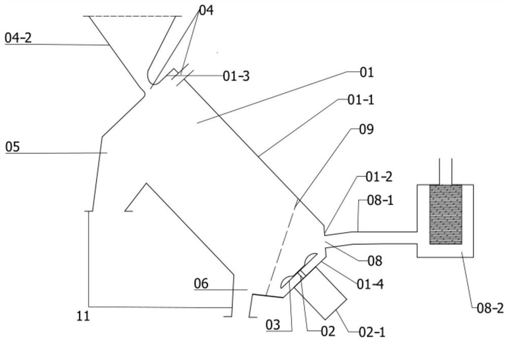
[0027] like figure 1 As shown, according to one aspect of the present application, the present application provides a cyclone screening equipment, specifically: a cyclone air separator, which mainly includes:

[0028] Cylinder body 01, the cylinder body 01 is a cylindrical container composed of a side wall 01-1, a tapered side wall 01-2, an upper end surface 01-3 and a lower end surface 01-4;

[0029] The lower end face 01-4 is provided with a drive shaft 02, and the drive shaft 02 is located on the central axis of the cylinder 01;

[0030] Centrifugal fan blades 03 are arranged on the drive shaft 02;

[0031] A feeding port 04 is opened on the upper end face 01-3 or on the side wall 01-1 close to the upper end face;

[0032] The area of ​​the side wall 01-1 close to the upper end face 01-3 is provided with a first discharge port 05; the area of ​​the joint of the side wall 01-1 and the tapered side wall 01-2 is provided with a second outlet Outlet 06;

[0033] The opening...

Embodiment 2

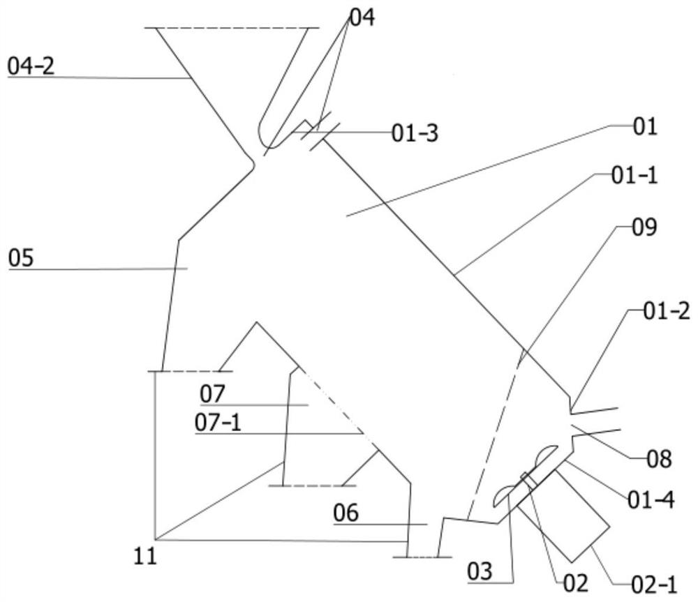
[0041] According to another aspect of the present application, on the basis of Embodiment 1 of the present application, the present application provides a cyclone screening device, specifically an integrated screening machine.

[0042] like figure 2 As shown, specifically, on the basis of Embodiment 1, a third discharge port 07 is opened on the side wall 01-1;

[0043] The third discharge port 07 is located in the middle of the side wall 01-1, and is located between the first discharge port 05 and the second discharge port 06;

[0044] The opening direction of the third discharge port 07 is downward or downward;

[0045] The third discharge port 07 is provided with a third discharge port screen 07-1, and the third discharge port screen 07-1 is smoothly and tightly connected with the inner wall of the cylinder.

[0046] The specific working principle of the second embodiment of the present application is as follows: as in the first embodiment, the upwardly moving light mater...

Embodiment 3

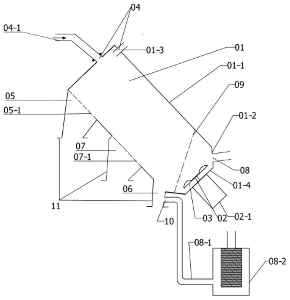
[0048] According to another aspect of the present application, on the basis of the second embodiment of the present application, the present application provides a cyclone screening device, specifically a cyclone screening machine.

[0049] like image 3 As shown, specifically, on the basis of Embodiment 2, a first discharge port screen 05-1 is installed on the first discharge port 05;

[0050] The aperture of the first outlet screen 05-1 is smaller than or equal to the aperture of the third outlet screen 07-1 installed in the third outlet 07;

[0051] The first discharge port screen 05-1 is smoothly and tightly connected with the inner wall of the cylinder.

[0052] This embodiment is suitable for occasions where there is no floc in the material and fine powders or particles of different particle sizes need to be separated. The specific working principle is as follows: the drive shaft drives the centrifugal fan blades to rotate, and a rotating airflow is formed inside the cy...


PUM


Abstract

The invention aims to provide rotational flow screening equipment. A relatively sealed cylindrical container composed of a side wall, a conical side wall, an upper end face and a lower end face is designed; a driving shaft is arranged on the end surface of the lower part, so that the driving shaft is positioned on the central axis of the barrel body; centrifugal fan blades are arranged on the driving shaft; a feeding hole is formed in the upper end surface or the side wall close to the upper end surface; a first discharging opening is formed in the area, close to the upper end face, of the side wall; a second discharge hole is formed in a combined part area of the side wall and the conical surface side wall; the opening directions of the first discharge port and the second discharge port are both downward or inclined downward, so that airflow circulates in the barrel, the quantity of air flowing out of the barrel is small, the influence of dust on the external environment in the working process is small, closed dust-free operation can be achieved, and the working efficiency is improved. Screening and winnowing can be synchronously completed on materials containing light floccules, and convenience and rapidness are achieved.

Description

technical field [0001] The present application relates to the technical field of industrial equipment, and in particular, to a cyclone screening equipment. Background technique [0002] Screening machines are commonly used equipment in the current industrial field. There are three main types of existing screening machines: one is an oscillating screener; the other is a drum screener; the third is an air separator. The main function of the first two types is to separate solid particles of different particle sizes, and the main function of the third type is to separate light flocs, such as seed coats and broken leaves in agricultural products. The existing screening technology mainly has the following defects: First, the screen needs to vibrate, rotate and other actions during the screening process, so the screening process cannot be completed in a closed chamber, and the dust is flying during the working process, which is relatively polluting to the environment. The second i...

Claims


Application Information

Patent Timeline
Patent Type & Authority Applications(China)
IPC IPC(8): B04C5/081B04C5/14
CPCB04C5/081B04C5/14Y02W30/62
Inventor 刘春李建桥
Owner BEIJINGLANDINGKECHUANG EQUIP TECH CO LTD
Why Eureka
Try Eureka