Die washing device for integrated circuit packaging die

A technology for integrated circuits and moulds, which is applied to cleaning methods using tools, cleaning methods and utensils, and cleaning methods using liquids. Effect

Inactive Publication Date: 2022-07-08
刘凯
View PDF0 Cites 0 Cited by
  • Summary
  • Abstract
  • Description
  • Claims
  • Application Information

AI Technical Summary

Problems solved by technology

[0003] When packaging integrated circuits, it is necessary to use packaging molds for molding, and then it is necessary to clean the packaging molds. At this time, it is often necessary to use a mold washing device. The current mold washing devices are generally simple in structure. Due to the different shapes of the packaging molds, it makes When cleaning the packaging mold, it is not easy to quickly clean the mold groove, resulting in time-consuming and laborious cleaning

Method used


Image

  • Die washing device for integrated circuit packaging die
  • Die washing device for integrated circuit packaging die
  • Die washing device for integrated circuit packaging die

Examples


Embodiment 1

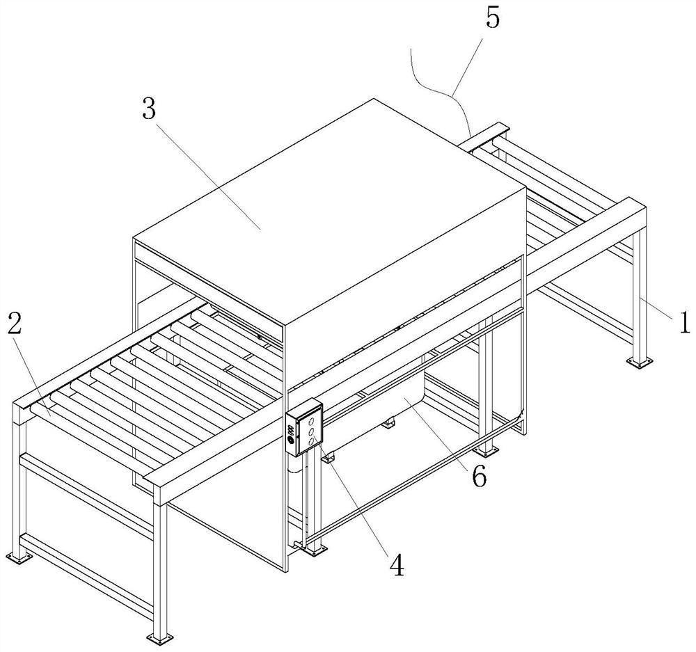
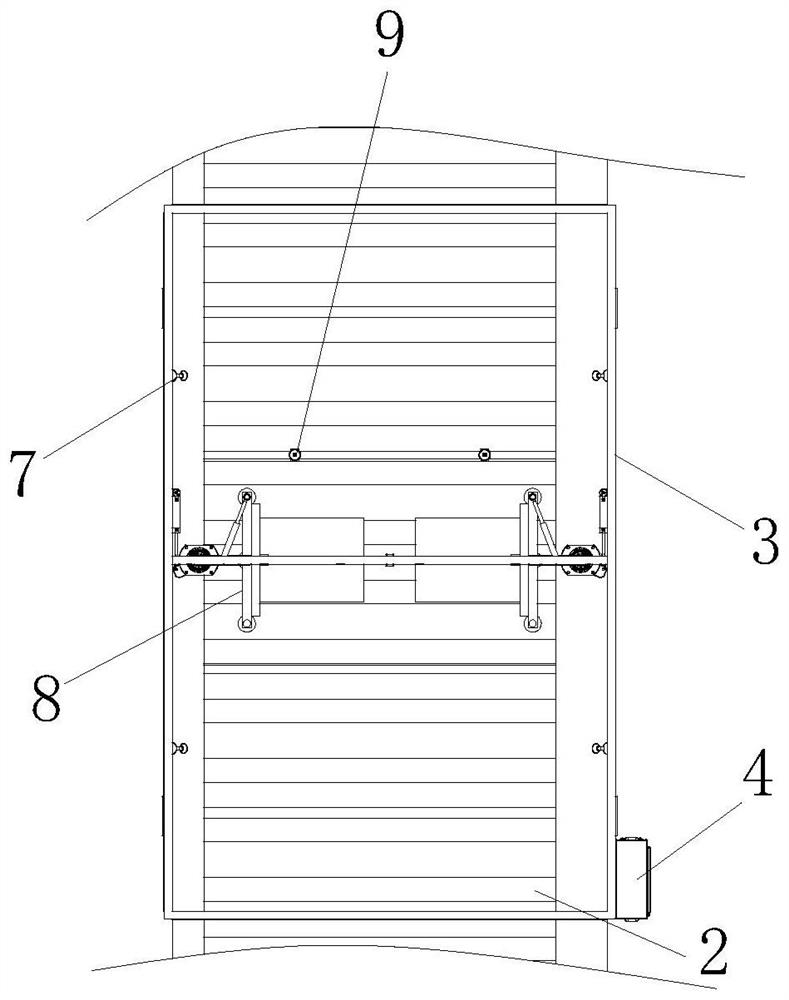
[0034] see figure 1 and figure 2 , the present invention provides a mold cleaning device for integrated circuit packaging molds by improvement, including a support frame 1, a transfer roller 2, a fixed frame 3, a control panel 4, a power supply wire 5, a circulation frame 6, a first nozzle 7 , the second nozzle 9 and the adjusting brushing mechanism 8, the inner side of the support frame 1 is provided with a transmission roller 2, the middle of the support frame 1 is provided with a fixed frame 3, the adjusting brushing mechanism 8 is installed on the inner side of the fixed frame 3, and the right end of the fixed frame 3 is provided with a The control panel 4, the rear end of the support frame 1 is fixed with a power supply wire 5, the bottom of the support frame 1 is installed with a circulation frame 6, the left and right sides of the fixed frame 3 are oppositely arranged with a first spray head 7, and the bottom of the support frame 1 and the second spray head 9 are conne...

Embodiment 2

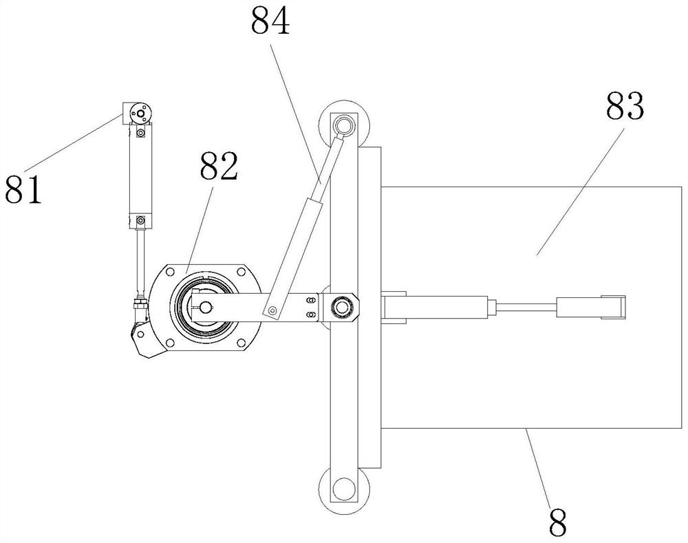
[0041] The present invention provides a mold washing device for integrated circuit packaging molds by improving, the rotating shaft 824 runs through the inner side of the movable sleeve 825, which is beneficial to make the rotating shaft 824 rotate smoothly, and the swing arm 826 is in the shape of a flat strip. , which is beneficial to drive the brush plate mechanism 83 to move. There are two adjustment brush mechanisms 8, and the adjustment brush mechanisms 8 are arranged along the left and right sides of the fixed frame 3 relative to each other.

[0042] The present invention provides a mold cleaning device for an integrated circuit packaging mold through improvement, and its working principle is as follows;

[0043] First, before use, place the mold washing device for the integrated circuit packaging mold horizontally, so that the support frame 1 can support the device fixedly;

[0044] Second, when in use, connect the external power supply through the power lead 5 to prov...


PUM


Abstract

The invention discloses a mold cleaning device for an integrated circuit packaging mold, which comprises a support frame, a conveying roller, a fixed frame, a control panel, a power supply wire, a circulating frame, a first spray head, a second spray head and an adjusting brushing mechanism, the conveying roller is arranged on the inner side of the support frame, the fixed frame is arranged in the middle of the support frame, and the adjusting brushing mechanism is arranged on the inner side of the fixed frame. According to the mold cleaning device, the adjusting brushing mechanisms are arranged in the fixing frame, the swinging mechanism drives the brushing plate mechanisms to swing, so that the distance between the two brushing plate mechanisms is adjusted, molds with different widths can be cleaned, then the brushing plate mechanisms are driven by the inclining mechanism to swing, and the mold cleaning effect is improved. The cleaning roller and the brush head can make contact with the two side walls and the top of the mold, and the advantage that the integrated circuit packaging mold can be rapidly cleaned is achieved.

Description

technical field [0001] The invention relates to the related field of integrated circuit packaging, in particular to a mold washing device for an integrated circuit packaging mold. Background technique [0002] The position of the integrated circuit package in the electronics pyramid is both the apex of the pyramid and the base of the pyramid. It is well-founded that it is in both positions at the same time. From the perspective of the density of electronic components (such as transistors) Said, ICs represent the cutting edge of electronics. [0003] When packaging an integrated circuit, the packaging mold needs to be used for molding, and then the packaging mold needs to be cleaned. At this time, a mold washing device is often used. The current mold washing device is generally simple in structure. Due to the different shapes of the packaging molds, the When cleaning the package mold, it is not easy to quickly clean the mold groove, resulting in time-consuming and laborious ...

Claims


Application Information

Patent Timeline
IPC IPC(8): B29C33/72B08B1/02B08B3/02
CPCB29C33/72B08B3/024B08B1/12B08B1/20
Inventor 刘凯
Owner 刘凯
Why Eureka
Try Eureka