
Plastic fan coil

A fan coil and plastic technology, applied in the direction of mechanical equipment, space heating and ventilation, space heating and ventilation details, etc., can solve the problems of prone to bacteria breeding, accumulation of foreign matter on the surface of the filter, and difficult equipment

Active Publication Date: 2022-07-08
江西旺来科技有限公司
View PDF7 Cites 1 Cited by
  • Summary
  • Abstract
  • Description
  • Claims
  • Application Information

AI Technical Summary

Problems solved by technology

[0003] However, in the existing technology, the existing fan coil units only filter the air injected into the equipment through the filter plate during actual use, and after a long period of actual use, it is easy to cause more foreign matter to accumulate on the surface of the filter screen, which in turn causes the outside air to enter the equipment more easily. Difficulty, which leads to poor actual use effect of the equipment. At the same time, when the external humidity is high, it is easy to cause the surface of the filter to be wet, which is easy to breed bacteria, resulting in a decrease in the actual use effect of the equipment.

Method used


Image

  • Plastic fan coil
  • Plastic fan coil
  • Plastic fan coil

Examples


Embodiment 1

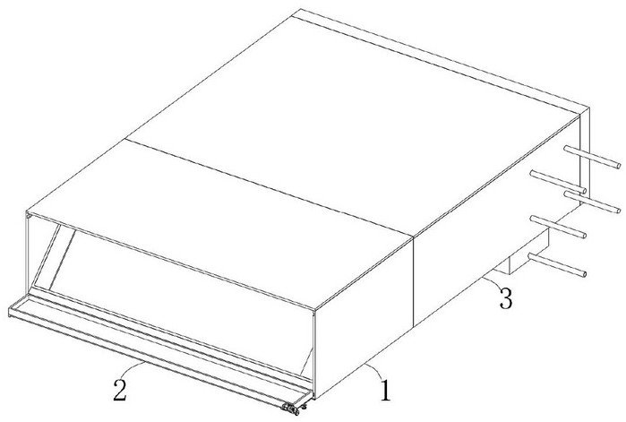
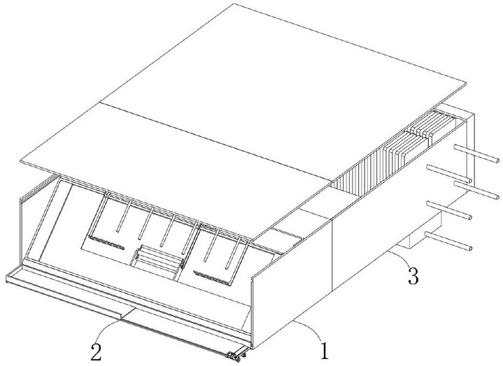
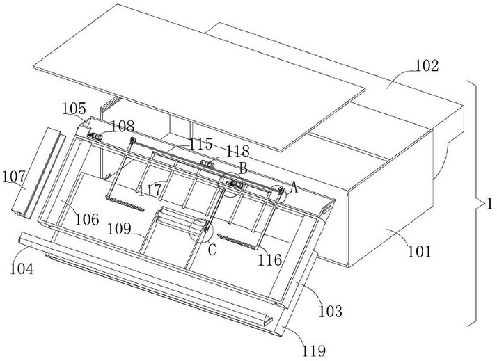
[0031] refer to Figure 1-Figure 9: Plastic fan coil unit, including: filter mechanism 1, storage mechanism 2 and functional mechanism 3, filter mechanism 1 includes bottom frame 101 and cleaning parts, the establishment of bottom frame 101 provides the installation basis for setting other functional parts of the equipment, and at the same time can Effective protection of other functional components of the equipment, the inner surface walls on both sides of the bottom frame 101 are provided with a first chute, which facilitates the installation of the top frame 105 through the establishment of the first chute. A top frame 105 is slidably embedded between the top frame 105, and the installation of other functional components of the equipment is facilitated by the establishment of the top frame 105. The inner surface walls on both sides of the bottom frame 101 are provided with a second chute, which is convenient for the establishment of the second chute. For the installation an...


PUM


Abstract

The plastic fan coil comprises a filtering mechanism, the filtering mechanism comprises a bottom frame and a cleaning part, first sliding grooves are formed in the inner surface walls of the two sides of the bottom frame, a top frame is slidably embedded between the interiors of the two first sliding grooves, second sliding grooves are formed in the inner surface walls of the two sides of the bottom frame, and a cushion frame is slidably embedded between the interiors of the two second sliding grooves; a mounting frame is fixedly connected between the opposite outer surfaces of the top frame and the cushion frame. During use, a fan is controlled to be started, so that external air can be effectively sucked into the bottom frame through a filter screen, and meanwhile, a rotating motor is controlled to be started in a timing manner, so that the rotating motor can effectively drive a corresponding supporting shaft to rotate through a bevel gear; furthermore, the supporting shafts can effectively drive the corresponding supporting rollers to rotate, and the rotating supporting rollers can effectively rotate to adjust the use surface of the filter screen.

Description

technical field [0001] The invention belongs to the technical field of fan coil unit equipment, in particular to a plastic fan coil unit. Background technique [0002] Fan coil unit is referred to as fan coil unit, which is one of the end devices of the air conditioning system composed of small fans, motors and coils. Cooling, dehumidifying or heating to adjust indoor air parameters, it is a commonly used cooling and heating terminal device. [0003] However, in the prior art, during the actual use of the existing fan coil units, the air injected into the equipment is mostly filtered through the filter plate, and after a long period of actual use, it is easy to cause more foreign objects to accumulate on the surface of the filter screen, thereby causing the outside air to enter the equipment. Difficulties, resulting in poor actual use effect of the equipment, and at the same time when the external humidity is high, it is easy to cause the surface of the filter screen to be ...

Claims


Application Information

Patent Timeline
Patent Type & Authority Applications(China)
IPC IPC(8): F24F1/0073F24F8/108F24F8/22F24F13/28F24F8/90
CPCF24F1/0073F24F8/108F24F8/22F24F13/28F24F8/90Y02B30/70
Inventor 湛彩虹黄敏惠黄福旺
Owner 江西旺来科技有限公司
Learn More