
Photovoltaic panel support for pinnacle house

A photovoltaic panel and photovoltaic panel technology, which is applied to the support structure of photovoltaic modules, photovoltaic power generation, photovoltaic modules, etc., can solve the problems of difficult realization of installation brackets, installation and fixation, etc., to meet the installation angle, prevent water leakage, and improve lighting efficiency. Effect

Pending Publication Date: 2022-07-08
绍兴日森新能源开发有限公司
View PDF0 Cites 0 Cited by
  • Summary
  • Abstract
  • Description
  • Claims
  • Application Information

AI Technical Summary

Problems solved by technology

[0004] Spire houses have slopes on both sides. The slopes are composed of multiple beams and tiles or other covering layers or covering layers laid on them. Therefore, traditional installation cannot be directly fixed on the spiers. Moreover, the spiers themselves have a certain Slope, the angle after installation of photovoltaic panels needs to be adjusted on the basis of the slope of the roof of the tiled house, which is difficult to achieve for ordinary installation brackets

Method used


Image

  • Photovoltaic panel support for pinnacle house
  • Photovoltaic panel support for pinnacle house
  • Photovoltaic panel support for pinnacle house

Examples


Embodiment 1

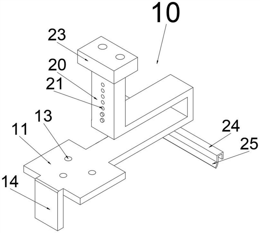
[0027] When the beam is made of wood, metal pipe and other materials that are easy to be bolted on, the adjustable mounting bracket 10 without the clip teeth 12, the clips 16, the pressing screw 17, the extrusion head 18 and the knob 19 is used for installation, so as to reduce the number of brackets. The overall weight of this adjustable mounting bracket 10 is structured as figure 1 shown.

[0028] When using this adjustable mounting bracket 10 for installation, such as Figure 4 As shown, remove the tiles or other covering layers corresponding to the beam, place the mounting frame 11 on the upper end surface of the beam, the baffle 14 is against the side of the beam, and drive the screws into the beam through the screw holes 13 to complete the mounting frame 11 To fix, stick the adhesive tape 25 on the adjacent tiles or other covering layers on the lower side, and put the removed tiles or other covering layers into the opening of the mounting frame 11. At this time, the upp...

Embodiment 2

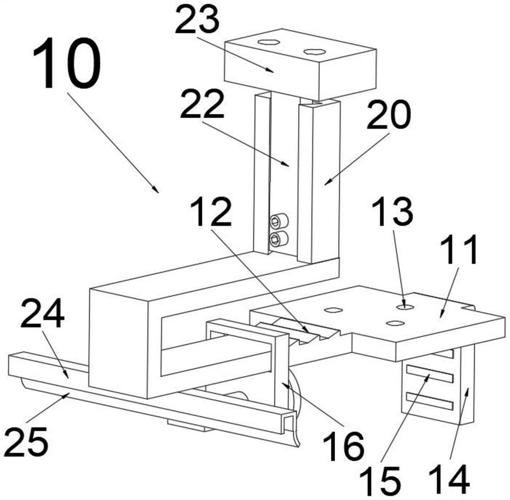
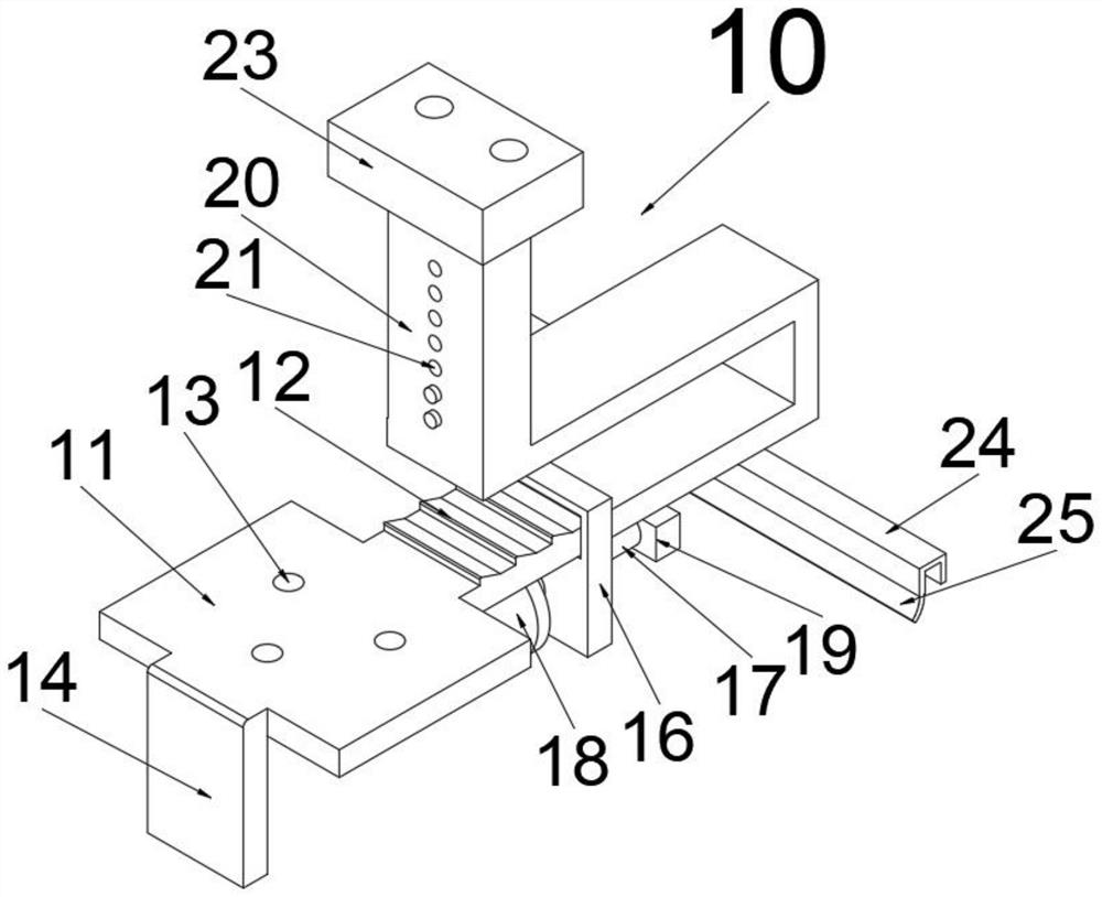
[0034] When the beam is made of concrete, stone and other materials that cannot be installed by screws, the adjustable mounting bracket 10 with the clamping teeth 12, the buckles 16, the pressing screw 17, the extrusion head 18 and the knob 19 is used for installation. The structure of the mounting bracket 10 is as follows Figure 2-3 shown.

[0035] When the adjustable mounting bracket 10 is used for installation, the tiles or other covering layers corresponding to the beam are removed, and the mounting bracket 11 is placed on the upper end face of the beam. The position of the buckle 16, the buckle 16 is stuck at the appropriate tooth 12, the knob 19 is rotated, the knob 19 drives the pressing screw 17 to rotate, and the pressing screw 17 moves in the buckle 16 through the thread meshing transmission, and the pressing screw 17 Drive the extrusion head 18 to move in the direction of the baffle 14 until the extrusion head 18 presses the beam tightly, and the extrusion head 18...


PUM


Abstract

The invention relates to a photovoltaic panel support for a pinnacle house, the photovoltaic panel support comprises an adjustable mounting support and a clamping device, the clamping device can be mounted on the adjustable mounting support, the adjustable mounting support comprises a mounting rack, screw holes, a baffle, a lifting seat, a lifting sliding block, a mounting head, a waterproof strip and an adhesive tape, the mounting rack is in a C shape, and the screw holes are arranged on the mounting rack. By means of the ingenious support structure, the support can be installed on the cross beams of the roof of the tile-roofed house, the overall appearance is not affected, meanwhile, the effect of tiles or other covering layers is kept, water leakage is prevented, multiple installation methods are adopted, the support can be installed through screws and a clamping mode, and the support can be fixed to the cross beams made of different materials; and the height of the support and the clamping angle of the clamping plate can be adjusted according to the installation requirements, so that the installation angle of the photovoltaic panel is met, the installation stability is improved, the illumination efficiency of the photovoltaic panel is improved, and the photovoltaic panel is suitable for roofs with various gradients.

Description

technical field [0001] The present invention relates to the field of photovoltaic panel installation, in particular to a photovoltaic panel bracket used in a spired house. Background technique [0002] Distributed photovoltaic power generation system, also known as distributed power generation or distributed energy supply, refers to the configuration of smaller photovoltaic power supply systems at the user site or near the power site to meet the needs of specific users. With the development of more and more factories and civil houses, photovoltaic power generation systems are erected on the roofs. [0003] Among the current roof photovoltaic power generation solutions, most flat-roofed houses are easier to install. Since photovoltaic panels need to be installed at a certain angle to achieve maximum power generation efficiency, they need to be installed with brackets, while flat-roofed houses are easier to lay brackets. Easier to install. [0004] The spire house has slopes...

Claims


Application Information

Patent Timeline
Patent Type & Authority Applications(China)
IPC IPC(8): H02S20/30H02S20/23F24S25/615F24S25/636F24S25/70
CPCH02S20/30H02S20/23F24S25/615F24S25/636F24S25/70F24S2025/6006Y02E10/50Y02B10/10
Inventor 潘全梅潘全英陈松海
Owner 绍兴日森新能源开发有限公司
Learn More