Supercharge Your Innovation With Domain-Expert AI Agents!

Propulsion system for helicopter

A technology for propulsion systems and helicopters, which is applied in high-efficiency propulsion technology, rotorcraft, motor vehicles, etc., can solve the problems of high scale, high cost and complex structure of manufacturing and maintenance, and achieve the effect of shortening time.

Pending Publication Date: 2022-07-08
赛峰直升机引擎公司
View PDF0 Cites 0 Cited by
  • Summary
  • Abstract
  • Description
  • Claims
  • Application Information

AI Technical Summary

Problems solved by technology

As noted above, such turboshaft engines have a complex architecture requiring a relatively large number of parts and the scale and cost of manufacture and maintenance are relatively high

Method used


Image

  • Propulsion system for helicopter
  • Propulsion system for helicopter
  • Propulsion system for helicopter

Examples


Embodiment Construction

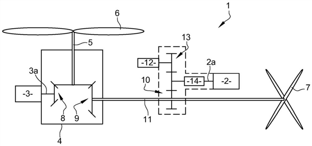
[0056] figure 1 A propulsion system 1 for a helicopter according to a first embodiment of the invention is shown. This includes a turboshaft engine 2 with a linked turbine, and an electric machine 3 operable as an electric motor.

[0057] Turboshaft engine 2 and electric machine 3 can rotate via main gearbox 4, main rotor 5 intended to be coupled to rotor 6 to form a single lift rotor, and anti-torque rotor 7 at the end of the beam at the rear of the helicopter fuselage.

[0058] Of course, the invention is not limited to this architecture, but can also be used where two concentric rotors ensure lift, so that the presence of anti-torque rotors is no longer necessary.

[0059] Specifically, the rotor 3a of the motor 3 is connected to the main rotor 5 via a first reducer formed by the gear 8 of the main gearbox, which first reducer provides the difference between the rotational speed of the main rotor 5 and the rotational speed of the rotor 3a of the motor 3 the first speed ra...


PUM


Abstract

A propulsion system (1) for helicopters, comprising a turboshaft engine (2) with a linked turbine and an electric machine (3) operable as an electric motor, said turboshaft engine (2) and said electric machine (3) being able to drive in rotation at least one main rotor (5) intended to be coupled to a rotary wing (6), characterized in that the main rotor (5) is driven by a motor (6). The invention relates to a propulsion system (1) comprising means (14) for coupling and decoupling, in rotation, between a rotor (3a) of said electric machine (3) and a rotor (2a) of said turboshaft engine (2), said coupling and decoupling means (14) being able to allow said rotor (2a) of said turboshaft engine (2) to be driven in rotation by means of said electric machine (3) in a first state of said propulsion system (1), the rotor (2a) of the turboshaft engine (2) and the rotor (3a) of the electric machine (3) are allowed to be decoupled in rotation in a second state of the propulsion system (1).

Description

technical field [0001] The present invention relates to a propulsion system for a helicopter. Background technique [0002] Helicopters are usually equipped with main rotors that drive the rotating wings to ensure their lift and propulsion. It is also known how to equip a helicopter with a tail rotor, also known as an anti-torque rotor (ATR), to counteract the torque exerted by the main rotor on the fuselage of the helicopter. [0003] In order to rotate the main rotor and, if necessary, the anti-torque rotor, the helicopter is equipped with a propulsion system comprising a turboshaft engine. Turboshaft engines may include so-called free turbines or so-called linked turbines. [0004] In the case of a free turbine engine, the first turbine (called the high pressure turbine) drives the compressor of the engine, while the second turbine (called the low pressure turbine) is connected to a gearbox (also known as the main gearbox or MGB) . The latter allows the speed to be re...

Claims


Application Information

Patent Timeline
IPC IPC(8): B64D35/08
CPCB64D35/08B64C27/12Y02T50/60B64D27/026B64D27/24
Inventor 罗曼·金·吉尔伯特·西里埃特奥利维厄·贝德里内安托伊雷·帕斯卡尔·毛陶克斯
Owner 赛峰直升机引擎公司
Features
  • R&D
  • Intellectual Property
  • Life Sciences
  • Materials
  • Tech Scout
  • Unparalleled Data Quality
  • Higher Quality Content
  • 60% Fewer Hallucinations
Learn More