Municipal water supply and drainage pipeline cleaning equipment

A pipeline cleaning, water supply and drainage technology, applied in the direction of cleaning hollow objects, cleaning methods and utensils, separation methods, etc., can solve the problems of increasing the difficulty of cleaning again, cleaning is not clean, etc., to improve the convenience of adjustment, improve the filtering effect, and ensure The effect of recycling

Pending Publication Date: 2022-07-12
厉磊
View PDF7 Cites 1 Cited by
  • Summary
  • Abstract
  • Description
  • Claims
  • Application Information

AI Technical Summary

Problems solved by technology

[0004] Based on the current way of cleaning the inside of the pipeline, it is all flushed by the high-pressure nozzle. During the cleaning process of the high-pressure nozzle, some stubborn dirt is difficult to wash off, so there is a problem that cleaning is not clean and it is difficult to clean again. The present invention proposes A municipal water supply and drainage pipeline cleaning equipment

Method used


Image

  • Municipal water supply and drainage pipeline cleaning equipment
  • Municipal water supply and drainage pipeline cleaning equipment
  • Municipal water supply and drainage pipeline cleaning equipment

Examples


Embodiment 1

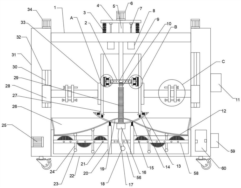
[0031]Referring to the drawings, a municipal water supply and drainage pipeline cleaning equipment includes a horizontal plate, the outer walls at both ends of the horizontal plate are fixedly connected with side plates, the bottom of the horizontal plate is provided with a pipe, the inner wall of the pipe is provided with a rotating box, the A first cleaning mechanism is arranged on the outer wall of one end of the rotating box, and a second cleaning mechanism is arranged on the outer wall of the other end of the rotating box. The outer walls of both ends are provided with splints, the other end of the splint is provided with a telescopic mechanism, the other end of the telescopic mechanism is provided with a height adjustment mechanism, the bottom of the pipe is provided with a bearing mechanism, and the two ends of the side plate are fixedly connected with a Bottom box, the inner wall of the bottom box is provided with a filtering mechanism, and the liquid supply mechanism i...

Embodiment

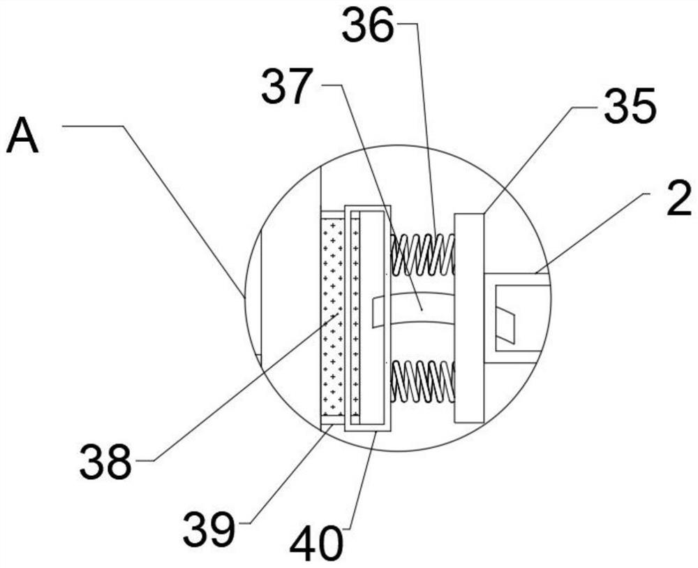
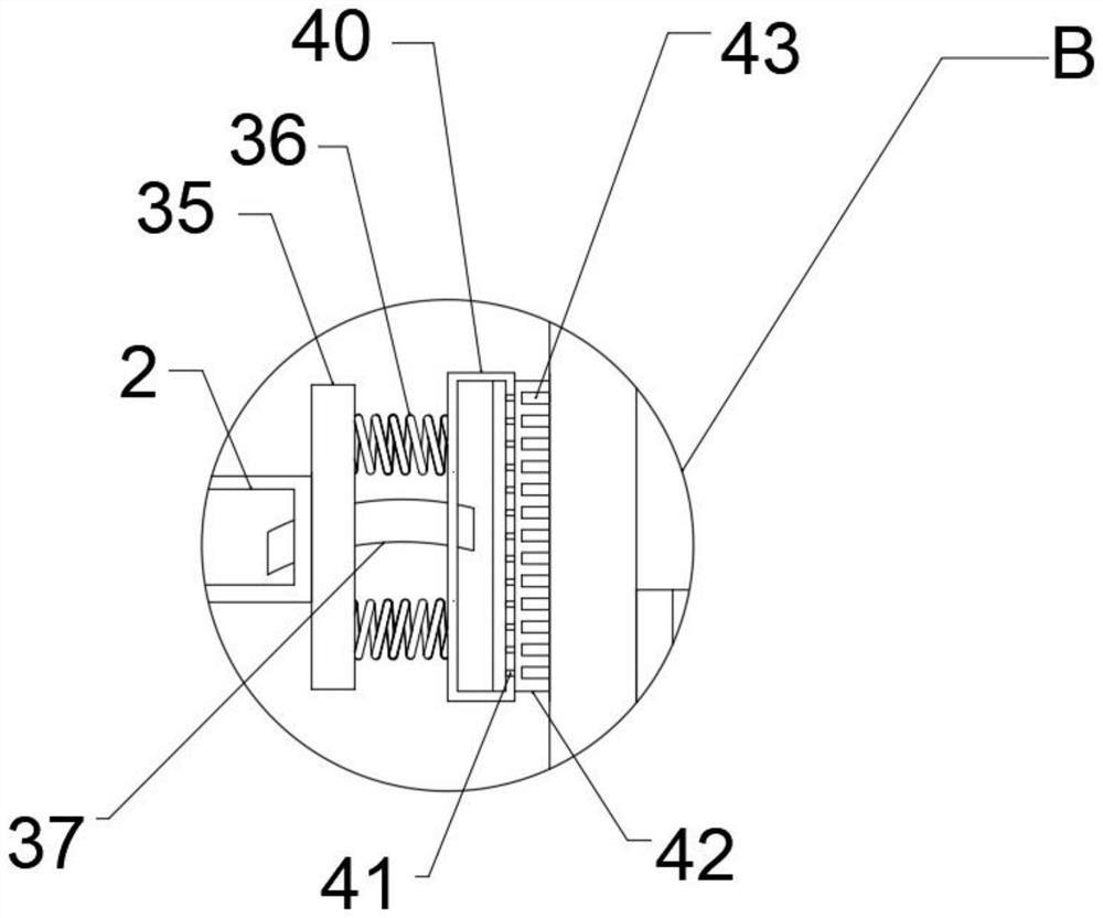
[0041] Referring to the figure, a municipal water supply and drainage pipeline cleaning equipment, the outer wall of the other end of the second connecting rod is fixedly connected with a fourth connecting plate, the outer wall of the other end of the fourth connecting plate is fixedly connected with a fifth spring, and the other end of the fifth spring and the splint Fixed connection, the outer wall of one end of the fourth connecting plate is fixedly connected with a cylinder.

[0042] When in use, the splint and the fourth connecting plate are connected by a fifth spring, so that the pipeline has the ability to move elastically, and the inclination angle of the splint and its pipeline can be adjusted by setting the air cylinder to achieve the purpose of multi-angle cleaning.

[0043] Example

[0044] Referring to the figure, a municipal water supply and drainage pipeline cleaning equipment, the bottom of the third spring is fixedly connected with a partition, both ends of t...


PUM


Abstract

The invention belongs to the technical field of cleaning equipment, and particularly provides the following scheme that the pipeline cleaning device comprises a transverse plate, the transverse plate is provided with a water inlet pipe, a water outlet pipe and a water outlet pipe, the water inlet pipe is provided with a water outlet pipe, and the water outlet pipe is provided with a water outlet pipe. Side plates are fixedly connected to the outer walls of the two ends of the transverse plate, a pipeline is arranged at the bottom of the transverse plate, and a rotating box is arranged on the inner wall of the pipeline. Water flow is introduced into the rotating box in the pipeline by arranging the liquid supply mechanism, the inner wall of the pipeline can be subjected to multiple rotary cleaning treatment by utilizing the first cleaning mechanism and the second cleaning mechanism on the outer wall of the rotating box by arranging the lifting rotating mechanism, and cleaning wastewater can be filtered by arranging the filtering mechanism in the bottom box; and by arranging the height adjusting mechanism, the position of the pipeline can be adjusted, and the adjusting convenience of the cleaning position is improved.

Description

technical field [0001] The invention relates to the technical field of cleaning equipment, in particular to a cleaning equipment for municipal water supply and drainage pipes. Background technique [0002] Drainage pipeline refers to the system of pipes and their ancillary facilities that collect and discharge sewage, waste water and rainwater. Including main pipes, branch pipes and pipes leading to the treatment plant, no matter they are built on the street or anywhere else, as long as the pipes are used for drainage, they should be counted as drainage pipes. However, the interior of the drainage pipes also needs to be cleaned up. During the use of the pipeline, crystals and dirt will be produced on the inner wall of the drainage pipe. These crystals and dirt adhere to the inner wall of the drainage pipe, making the passage of the pipe gradually smaller. If it is not cleaned in time, it will seriously affect the drainage pipe. use. [0003] At present, the way to clean th...

Claims


Application Information

Patent Timeline
Patent Type & Authority Applications(China)
IPC IPC(8): B08B9/043B01D29/03B01D29/50B01D33/35B01D36/02
CPCB08B9/0436B01D36/02B01D29/03B01D29/50B01D33/35
Inventor 厉磊张丹
Owner 厉磊
Why Eureka
Try Eureka