
Iron ore detector for geological exploration

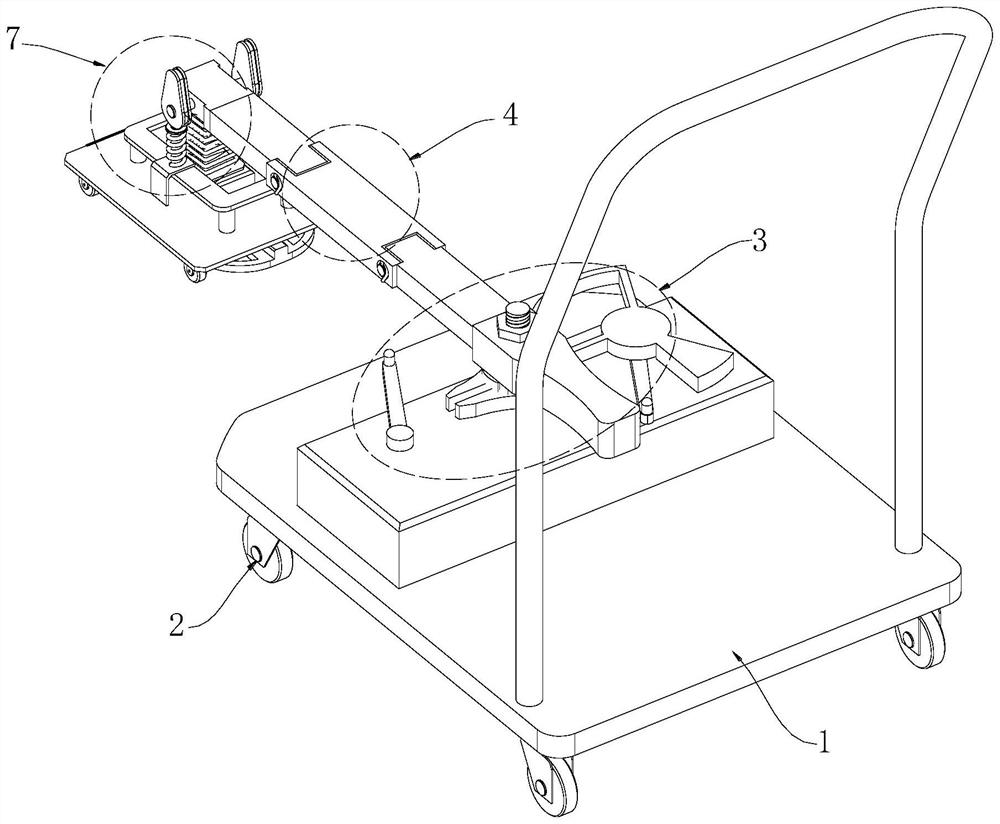
A geological exploration and detector technology, applied in the field of geological exploration, can solve the problems of manpower consumption and inability to improve the search efficiency, and achieve the effect of convenient excavation, reducing manpower operation and solving manpower consumption

Pending Publication Date: 2022-07-12
山东省地质矿产勘查开发局第一地质大队
View PDF0 Cites 0 Cited by
  • Summary
  • Abstract
  • Description
  • Claims
  • Application Information

AI Technical Summary

Problems solved by technology

[0004] Although the hand-held iron ore prospector is easy to carry, in geological exploration, the geological range that needs to be explored is huge. Only using manual hand-held methods in a wide range of areas will consume a lot of money in carpet search. Manpower, and can not improve the efficiency of the search, for this reason, we propose an iron ore detector for geological exploration

Method used


Image

  • Iron ore detector for geological exploration
  • Iron ore detector for geological exploration
  • Iron ore detector for geological exploration

Examples


Embodiment 1

[0044] The support plate 1 is provided with a driving member 3, the driving end of the driving member 3 is provided with a swing rod 4, and the end of the swing rod 4 away from the driving member 3 is provided with an iron ore detection head 5 for detecting the position of the iron ore;

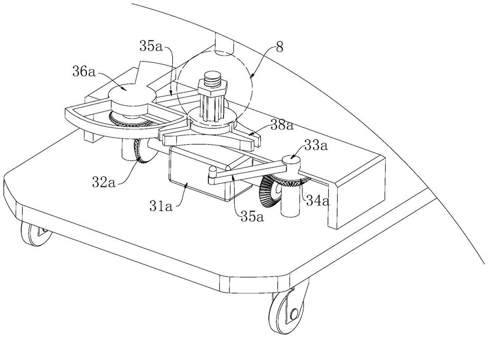
[0045]The driving member 3 includes a biaxial motor one 31a mounted on the support plate 1. The output end of the biaxial motor one 31a is provided with a driving gear 32a, and the end of the mounting seat 31b close to the driving gear 32a is provided with a rotating shaft 33a. A driven gear 34a is provided, and the driving gear 32a meshes with the driven gear 34a;

[0046] The rotating shaft 33a passes through the top of the mounting seat 31b and is respectively connected with a toggle rod 35a, and the top of any group of toggle rods 35a is provided with a matching ring 36a;

[0047] A passive ring 37a is arranged at the middle position of the mounting seat 31b, and a toggle groove 38a is op...

Embodiment 2

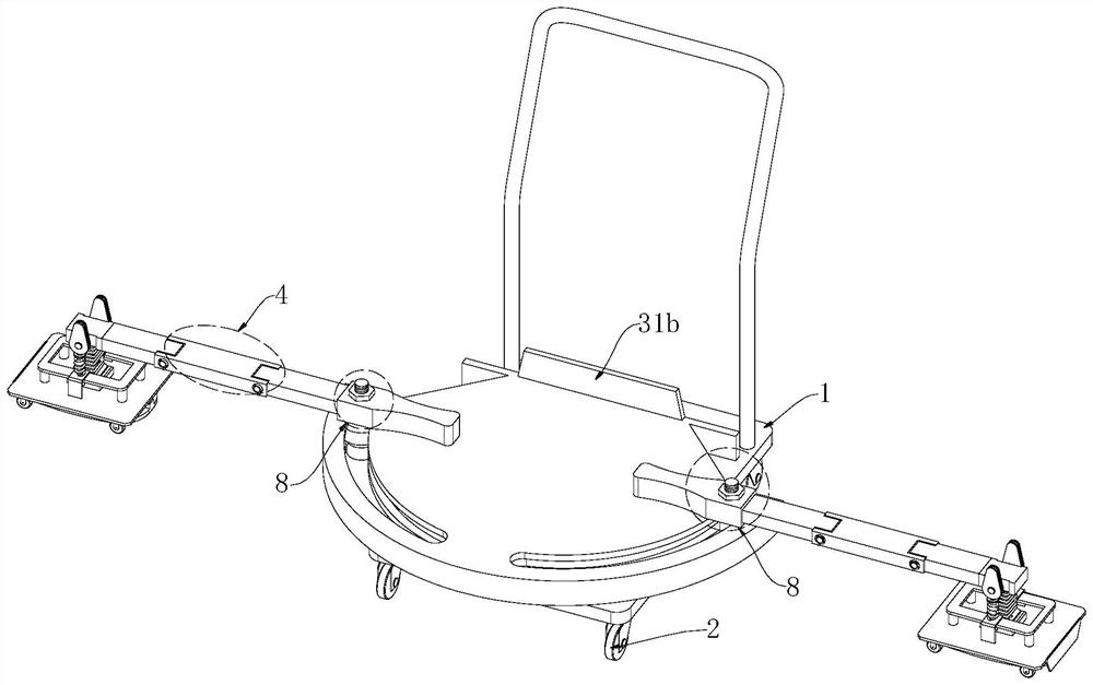
[0064] The driving member 3 includes a mounting seat 31b installed on the support plate 1, and two sets of sliding grooves 32b are opened on the mounting seat 31b. The sliding groove 32b is provided with a moving block 1 33b, the moving block one 33b is connected with the swing rod 4, and the moving block one 33b is connected. A detachable connecting piece 8 is provided between the swing rod 4;

[0065] One end of the mounting seat 31b is provided with a rotating motor 34b, the output end of the rotating motor 34b is provided with a threaded rod 35b, the threaded rod 35b is provided with a second moving block 36b, the moving block one 33b is movably connected with the moving block two 36b, and the moving block two A limiter 9 is arranged between 36b and the mounting seat 31b;

[0066] The limiting member 9 includes a connecting block 91 mounted on the mounting seat, and a limiting slot 92 is defined on the connecting block 91;

[0067] The two sides of the moving block 36b ar...


PUM


Abstract

The invention discloses an iron ore detector for geological exploration, which comprises a supporting plate, a plurality of groups of moving wheels are arranged at the bottom of the supporting plate, a driving part is arranged on the supporting plate, a swing rod is arranged at the driving end of the driving part, and an iron ore detection head for detecting the position of iron ore is arranged at one end, far away from the driving part, of the swing rod. According to the iron ore detector for geological exploration, the iron ore detection head can be automatically driven to conduct periodic swing detection through the arranged driving piece, carpet type searching can be conducted in geological exploration, meanwhile, the iron ore detection head can be automatically driven to conduct periodic swing detection, and the detection efficiency is greatly improved. According to the invention, the search range can be expanded when detection is carried out at a certain position, and manual operation can be reduced by utilizing self-automatic swinging, so that the problem of manpower consumption is solved, and the search efficiency can be improved.

Description

technical field [0001] The invention relates to the technical field of geological exploration, in particular to an iron ore detector for geological exploration. Background technique [0002] Geological exploration is an investigation and research activity that uses various means and methods to conduct geological exploration and detection to determine the appropriate bearing layer, determine the foundation type and calculate the basic parameters according to the bearing capacity of the bearing layer. It is the discovery of industrially significant deposits in the mineral census, in order to find out the quality and quantity of minerals, as well as the technical conditions for mining and utilization, to provide mineral reserves and geological data required for mine construction and design, and to analyze the rocks and strata in a certain area. , structure, minerals, hydrology, landforms and other geological conditions to conduct investigation and research work. Iron is the ea...

Claims


Application Information

Patent Timeline
Patent Type & Authority Applications(China)
IPC IPC(8): G01V9/00
CPCG01V9/00
Inventor 廉永彪李建王荣柱张鼎
Owner 山东省地质矿产勘查开发局第一地质大队
Learn More