Contact connection auxiliary structure for microswitch

A technology of auxiliary structure and micro switch, which is applied in the direction of contact electrical connection, contact, parts of flip switch/rocker switch, etc., which can solve the problem of circuit disconnection, poor current flow and unstable circuit connection of the switch and other problems, to achieve the effect of increasing the contact area, avoiding unstable circuit connection, and realizing conversion

Pending Publication Date: 2022-07-12
WUXI SENIOR TECH CO LTD
View PDF0 Cites 3 Cited by
  • Summary
  • Abstract
  • Description
  • Claims
  • Application Information

AI Technical Summary

Problems solved by technology

[0003] In the prior art, most of the contacts of traditional micro switches are connected by means of inserts. When the switch is turned on, the two guides have a certain angle, which leads to poor flow of current and easily leads to short circuit. , and the touch rocker outside the micro switch needs to be pressed with a constant force after being pressed. If it is pressed manually, the force is not accurately grasped, which will easily lead to the disconnection of the switch circuit and cause the circuit connection to be unstable.

Method used


Image

  • Contact connection auxiliary structure for microswitch
  • Contact connection auxiliary structure for microswitch
  • Contact connection auxiliary structure for microswitch

Examples


Embodiment 1

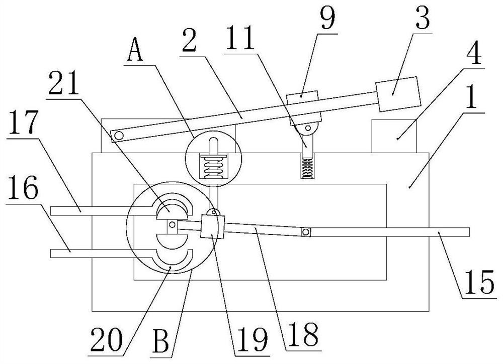
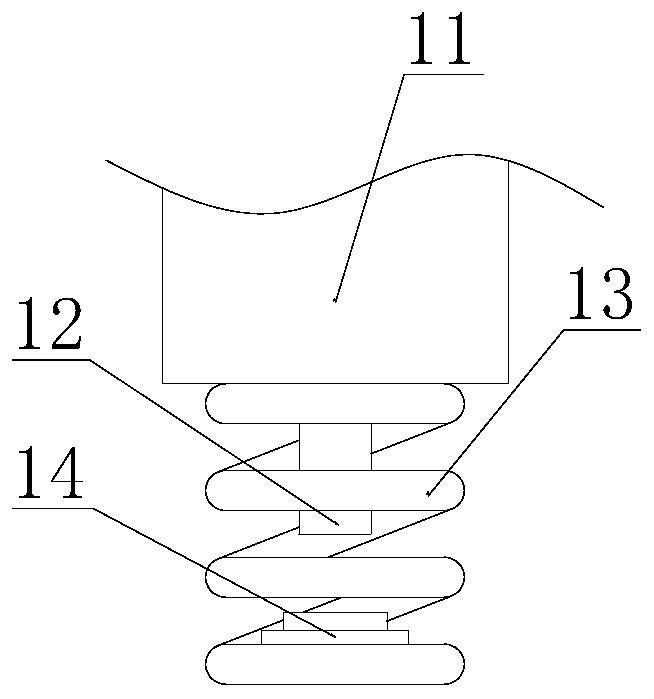
[0023] like Figure 1-2 and Figure 4 As shown, this specific embodiment adopts the following technical solutions: a contact connection auxiliary structure for a micro switch, comprising a housing 1, and a touch rocker 2 is rotatably connected to one end of the top of the housing 1, and the touch rocker 2. An iron block 3 is fixedly connected to one end away from the rotating shaft, and an electromagnet 4 is fixedly connected to the top of the casing 1 and one end close to the iron block 3. The electromagnet 4 is magnetically connected to the iron block 3 and is adsorbed by the electromagnet 4 The iron block 3 reduces the force required to press and touch the rocker 2, and avoids unstable circuit connection due to insufficient pressing force, wherein, the end of the rocker 2 close to the iron block 3 is cut with a chute 10, so The chute 10 is slidably connected with an I-shaped slider 9, the bottom of the I-shaped slider 9 is rotatably connected with a connecting rod 11, and ...

Embodiment 2

[0027] like figure 1 , image 3 As shown, this specific embodiment adopts the following technical solutions:

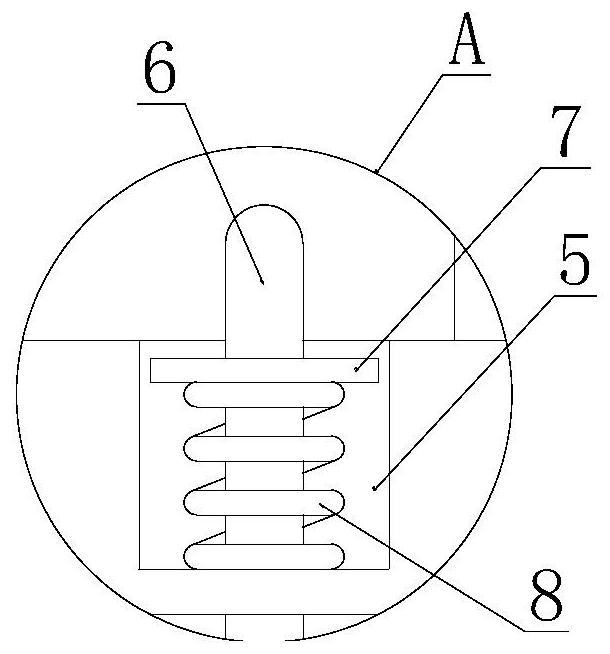
[0028] A telescopic slot 5 is excavated on the top of the casing 1 near the rotating shaft of the rocker 2, and a transmission rod 6 is inserted into the telescopic groove 5, and the transmission rod 6 extends to the inside of the casing 1; The casing 1 is provided with a telescopic groove 5 at the position relative to the transmission rod 6 , and one end of the transmission rod 6 is located inside the telescopic groove 5 and is fixedly connected to a limit plate 7 , and the bottom of the limit plate 7 is fixed between the bottom of the telescopic groove 5 A No. 1 spring 8 is connected, and one end of the transmission rod 6 is located inside the casing 1 with a No. 2 slider 19 . Connection, the No. 2 slider 19 is made of insulating material. When the transmission rod 6 is squeezed, the No. 2 slider 19 is driven to descend. The location of the access point.

[0029...

Embodiment 3

[0031] like figure 1 and Figure 5 As shown, this specific embodiment adopts the following technical solutions: one end of the housing 1 close to the electromagnet 4 is fixedly connected with a common wiring board 15, and one end of the housing 1 away from the electromagnet 4 is fixedly connected with a normally closed wiring board 16 and Normally open wiring board 17, between the common wiring board 15 and the normally closed wiring board 16 and the normally open wiring board 17 are provided with conductive rods 18 and conductive contacts 21, wherein the conductive rods 18 and the common wiring board 15 rotate Connecting, the normally closed wiring board 16 and the normally open wiring board 17 are located inside the casing 1 and both ends are fixedly connected with a U-shaped connecting piece 20, the concave surfaces of the two U-shaped connecting pieces 20 are opposite, and the conductive contacts 21 are located at between the two U-shaped connecting pieces 20 .

[0032] ...


PUM


Abstract

The invention discloses a contact connection auxiliary structure for a microswitch, which comprises a shell, one end of the top of the shell is rotatably connected with a touch seesaw, one end of the touch seesaw far away from a rotating shaft is fixedly connected with an iron block, one end of the top of the shell close to the iron block is fixedly connected with an electromagnet, and the electromagnet is magnetically connected with the iron block. When the touch switch is pressed downwards, an extrusion rod at the bottom of a connecting rod makes contact with the switch, an electromagnet attracts an iron block downwards, the iron block is attracted through the electromagnet, force needed for pressing the touch seesaw is reduced, and therefore the touch seesaw can be pressed conveniently. Unstable circuit connection caused by insufficient extrusion force is avoided; the U-shaped connecting sheets are arranged at the two wiring boards in the microswitch, and the upper end and the lower end of the conductive contact are arc-shaped, so that the contact area of the conductive sheets during circuit connection is increased, and short circuit caused by unsmooth current flow is avoided.

Description

Technical field: [0001] The invention belongs to the technical field of switch auxiliary accessories, in particular to a contact connection auxiliary structure for a micro switch. Background technique: [0002] The micro switch is a contact mechanism with a small contact interval and a snap-action mechanism, and the switch action is performed with a specified stroke and a specified force. There is a driving rod outside the switch. Because the contact distance of the switch is relatively small, it is called a micro switch. It is also called a sensitive switch, a quick switch actuated by pressure, and is widely used in door switches in anti-theft systems. [0003] In the prior art, the contacts of traditional micro switches are mostly connected by means of inserts. When the switch is turned on, the two guides have a certain angle, which leads to poor current flow and easy short circuit. , and the touch rocker outside the micro switch needs to be pressed with a constant force ...

Claims


Application Information

Patent Timeline
Patent Type & Authority Applications(China)
IPC IPC(8): H01H23/12H01H23/02H01H1/58H01H1/50
CPCH01H23/12H01H23/02H01H1/58H01H1/50
Inventor 孙莉
Owner WUXI SENIOR TECH CO LTD
Why Eureka
Try Eureka