Permanent magnet synchronous motor rotor and permanent magnet motor

A permanent magnet synchronous motor and rotor technology, applied in the direction of synchronous machine parts, motors, magnetic circuit rotating parts, etc., can solve the problem of low motor flux linkage, improve flux linkage, reduce demagnetization rate, and increase motor torque Effect

Pending Publication Date: 2022-07-12
ZHUHAI LANDA COMPRESSOR +1
View PDF0 Cites 0 Cited by
  • Summary
  • Abstract
  • Description
  • Claims
  • Application Information

AI Technical Summary

Problems solved by technology

[0005] Therefore, the technical problem to be solved by the present invention is to overcome the defect of low motor flux linkage in the permanent magnet motor in the prior art, thereby providing a permanent magnet synchronous motor rotor and a permanent magnet motor

Method used


Image

  • Permanent magnet synchronous motor rotor and permanent magnet motor
  • Permanent magnet synchronous motor rotor and permanent magnet motor
  • Permanent magnet synchronous motor rotor and permanent magnet motor

Examples


Embodiment Construction

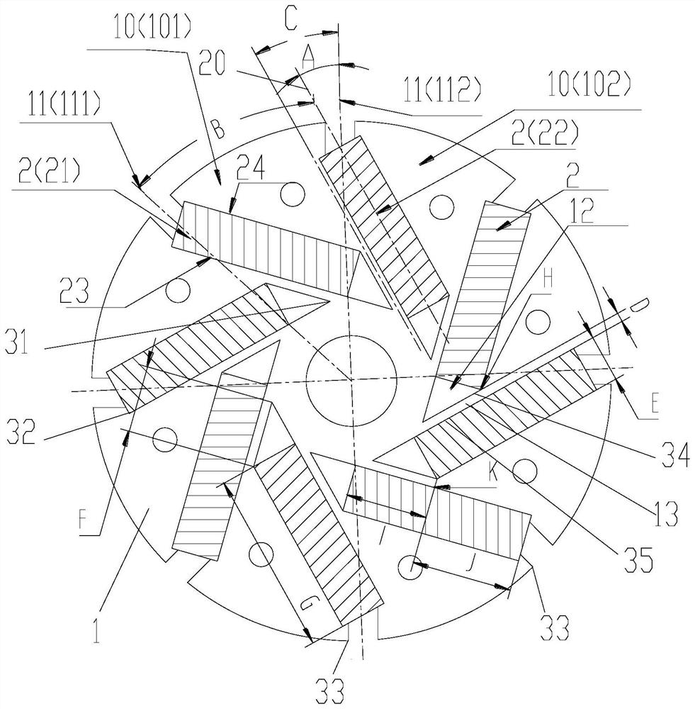
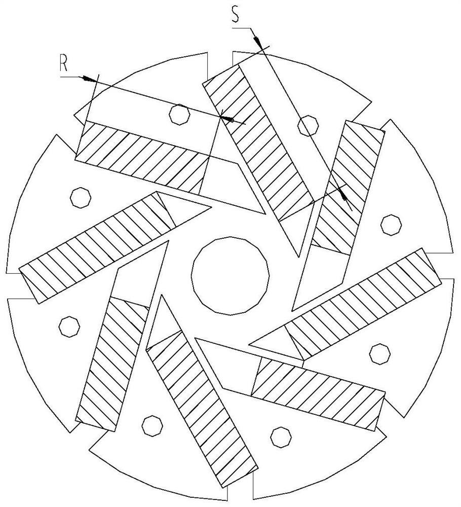
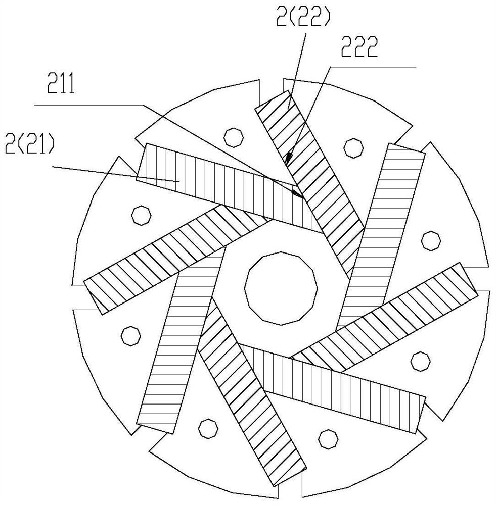
[0030] like Figure 1-7 As shown, the present invention provides a permanent magnet synchronous motor rotor, which includes: a rotor core 1 and a permanent magnet 2 (preferably a tangential permanent magnet, which is defined by the magnetization direction, and the magnetization direction is along the circumferential direction of the rotor, which is called a tangential permanent magnet). magnets), the permanent magnets 2 are arranged on the rotor core and extend in the radial direction of the rotor core, the number of the permanent magnets is N, N≥2, and the N permanent magnets 2 are arranged in sequence along the radial direction of the rotor core. The rotor cores 1 are arranged at intervals in the circumferential direction, and opposite sides of every two adjacent permanent magnets 2 have the same polarity;

[0031] Wherein, the permanent magnet 2 has a permanent magnet centerline 20 , the rotor includes a plurality of magnetic poles 10 (including a first magnetic pole 101 an...


PUM


Abstract

The invention provides a permanent magnet synchronous motor rotor and a permanent magnet motor, the permanent magnet synchronous motor rotor comprises a rotor core and N permanent magnets, the permanent magnets are arranged on the rotor core and extend along the radial direction of the rotor core, and the opposite sides of every two adjacent permanent magnets have the same polarity; the permanent magnet is provided with a permanent magnet center line, the rotor comprises a plurality of magnetic poles, a magnetic pole boundary line is arranged between two adjacent magnetic poles, the permanent magnet center line of the permanent magnet and the nearest magnetic pole boundary line are obliquely arranged, an included angle A not equal to 0 exists between the permanent magnet center line of the permanent magnet and the nearest magnetic pole boundary line, the angle of each magnetic pole in the circumferential direction of the rotor iron core is B, and A and B meet the following relation that A / B is larger than or equal to 0.2. According to the invention, the effective magnetic flux area of the permanent magnet is increased in the limited space of the rotor, the flux linkage of the motor is improved, the torque of the motor is improved, the running current of the motor is reduced, the efficiency of the motor is improved, the demagnetization rate of the permanent magnet is reduced, and the demagnetization resistance of the motor is improved.

Description

technical field [0001] The invention relates to the technical field of motors, in particular to a permanent magnet synchronous motor rotor and a permanent magnet motor. Background technique [0002] Due to the "magnetization" effect, the motor with the permanent magnet tangentially magnetized structure can generate a higher air gap flux density than the permanent magnet radially magnetized motor, so that the motor has a larger torque / current ratio and torque / volume ratio. , more and more are used in servo systems, electric traction, office automation, household appliances and other occasions. [0003] Because the tangential permanent magnet motor in the prior art adopts the magnetic circuit structure of a single permanent magnet in parallel, the working point of the permanent magnet of the rotor is lower than that of the radial permanent magnet motor, which is easy to cause the motor efficiency to decrease, and there is a risk of demagnetization in harsh environments, so tha...

Claims


Application Information

Patent Timeline
IPC IPC(8): H02K1/27H02K1/2746H02K21/02
CPCH02K1/27H02K1/2746H02K21/02H02K2213/03Y02T10/64
Inventor 王晶魏会军陈华杰刘进超张辉
Owner ZHUHAI LANDA COMPRESSOR
Why Eureka
Try Eureka