
Optical film with adhesive layer and liquid crystal panel

An adhesive layer, liquid crystal panel technology, applied in optics, optical components, nonlinear optics, etc., can solve the problems of liquid crystal molecular alignment disorder and poor display.

Pending Publication Date: 2022-07-12
NITTO DENKO CORP
View PDF1 Cites 0 Cited by
  • Summary
  • Abstract
  • Description
  • Claims
  • Application Information

AI Technical Summary

Problems solved by technology

If the liquid crystal display device is charged, the alignment of the liquid crystal molecules contained in the liquid crystal cell will be disordered, and display failure will occur.

Method used

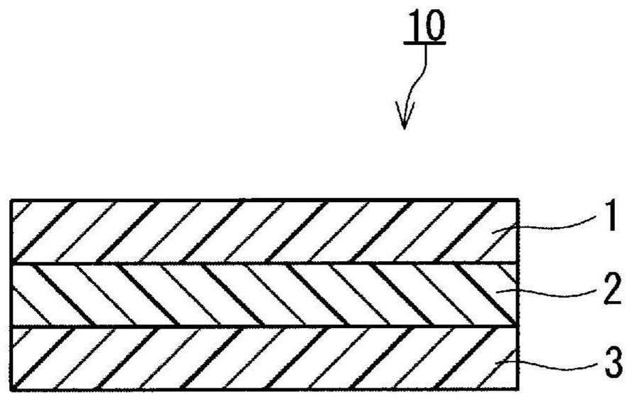
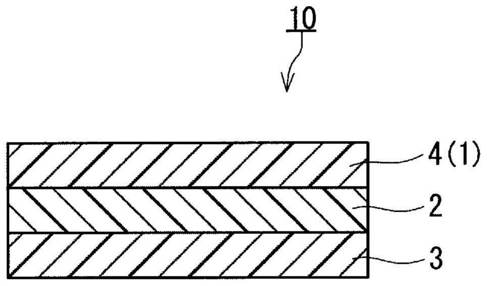
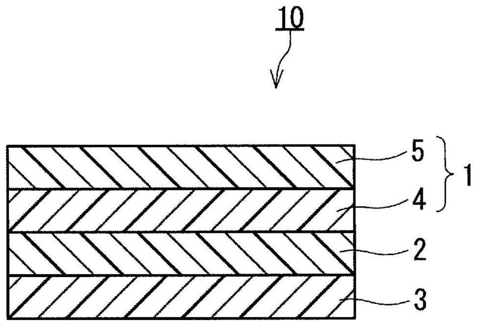

Image

  • Optical film with adhesive layer and liquid crystal panel
  • Optical film with adhesive layer and liquid crystal panel
  • Optical film with adhesive layer and liquid crystal panel

Examples


Embodiment 1

[0202] The antireflection layer AR1 with an adhesive layer is joined to the polarizer P1 side of the laminated body which consists of the polarizer P1 and the antistatic layer AE1. The bonding is performed through the pressure-sensitive adhesive layer included in the antireflection layer AR1. Next, the pressure-sensitive adhesive layer A was transferred onto the antistatic layer AE1 to obtain the pressure-sensitive adhesive layer-attached optical film of Example 1.

Embodiment 2

[0204] Except having used the laminated body which consists of polarizer P1 and antistatic layer AE2, it carried out similarly to Example 1, and obtained the optical film with an adhesive layer of Example 2.

Embodiment 3

[0206] Except having used the laminated body which consists of polarizer P1 and antistatic layer AE3, it carried out similarly to Example 1, and obtained the optical film with an adhesive layer of Example 3.


PUM

PropertyMeasurementUnit
thicknessaaaaaaaaaa
thicknessaaaaaaaaaa
thicknessaaaaaaaaaa

Abstract

The optical film with an adhesive layer is provided with an optical film and an adhesive layer, and is also provided with an antistatic layer containing a conductive polymer. The difference in light transmittance caused by the difference in the measurement region of the optical film with the adhesive layer is 2% or less as expressed by the difference between the maximum value and the minimum value of the light transmittance. Although the optical film with the adhesive layer is provided with an antistatic layer containing a conductive polymer, unevenness is not easily seen on the display surface of the liquid crystal panel.

Description

technical field [0001] The present invention relates to an optical film with an adhesive layer and a liquid crystal panel. Background technique [0002] The liquid crystal display device includes, for example, a liquid crystal panel having a structure in which an optical film such as a polarizer is disposed on the visible side than a liquid crystal cell, and an illumination system that irradiates the liquid crystal panel with light. A liquid crystal display device displays an image by applying a voltage to a liquid crystal cell and adjusting the alignment of liquid crystal molecules contained in the liquid crystal cell. [0003] In a liquid crystal display device, static electricity is generated during manufacture, for example, when an optical film is bonded to a liquid crystal cell via an adhesive layer, or during use, for example, when a user touches the liquid crystal display device. The liquid crystal display device may be charged due to this static electricity. When t...

Claims


Application Information

Patent Timeline
Patent Type & Authority Applications(China)
IPC IPC(8): G02B1/16B32B7/023B32B7/025B32B27/00B32B27/18G02B1/115G02B5/30G02F1/1335G09F9/00G09F9/30
CPCB32B7/023B32B7/025B32B27/00B32B27/18G02B1/115G02B1/16G02B5/30G02F1/1335G09F9/00G09F9/30G02F1/133509G02F1/133528
Inventor 山本悟士木村智之外山雄祐
Owner NITTO DENKO CORP
Learn More