
Knitting machine mesh wire pushing operation device and knitting machine

A technology of mesh wire and running device of a weaving machine, applied in the field of weaving machines, which can solve the problems of increasing the number of driving devices of the weaving machine, increasing production and later maintenance costs, and poor pushing effect, so as to ensure the weaving effect of the mesh wire, stable The effect of push and cost saving

Pending Publication Date: 2022-07-15
安平县顺威丝网机械制造有限公司
View PDF0 Cites 0 Cited by
  • Summary
  • Abstract
  • Description
  • Claims
  • Application Information

AI Technical Summary

Problems solved by technology

[0002] The knitting machine is the chain link fence machine, also known as the diamond net machine. It is a wire mesh machine that crochets low-carbon steel wire, stainless steel wire, aluminum alloy wire, PVC wire, and sprayed wire into a chain link fence. In the process of knitting mesh, the knitting machine usually needs to push the mesh. The existing knitting machine uses different driving devices for its pushing device, positioning needle device, and bucket device, that is, the pushing device uses a separate push device. The power device provides the pushing force, which not only has poor pushing effect, but also increases the number of driving devices of the knitting machine, increasing production and post-maintenance costs

Method used


Image

  • Knitting machine mesh wire pushing operation device and knitting machine
  • Knitting machine mesh wire pushing operation device and knitting machine
  • Knitting machine mesh wire pushing operation device and knitting machine

Examples


Embodiment 1

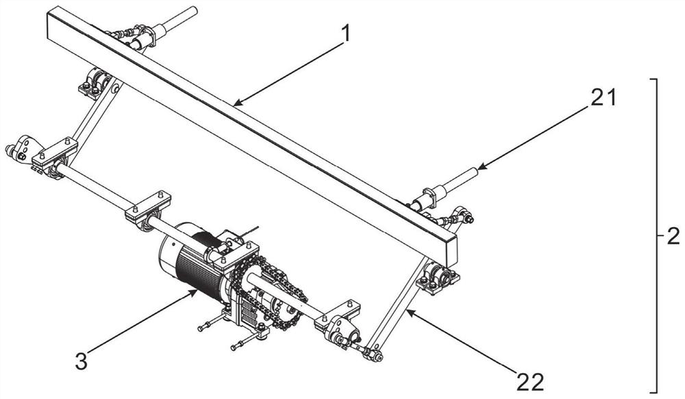
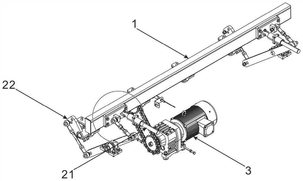
[0029] The invention provides a knitting machine mesh wire push running device, such as figure 1 and figure 2 As shown, the mesh wire pushing operation device of the knitting machine includes a mesh wire pushing mechanism 1 , a reciprocating transmission mechanism 2 and a driving mechanism 3 .

[0030] The linear reciprocating guide mechanism 21 is connected to the mesh wire pushing mechanism 1 , and the linear reciprocating guiding mechanism 21 can effectively limit the moving path of the mesh thread pushing mechanism 1 so that it can only move in a straight line.

[0031] The mesh pushing mechanism 1 is connected with the driving mechanism 3 through the reciprocating transmission mechanism 22 , and the reciprocating transmission transmission mechanism 22 can effectively convert the rotational power output by the driving mechanism 3 , thereby providing the mesh pushing mechanism 1 with a reciprocating pushing force.

[0032] The linear reciprocating guide mechanism 21 and t...

Embodiment 2

[0035] Embodiment 2 is built on the basis of embodiment 1:

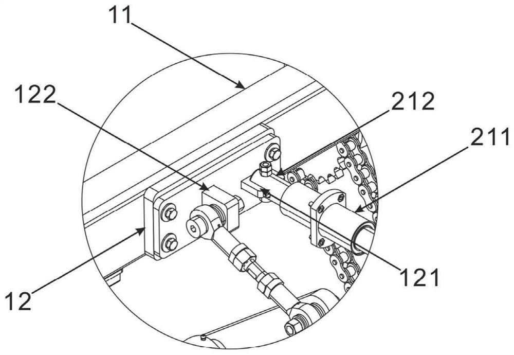
[0036] like image 3 As shown, the mesh pushing mechanism 1 includes a push plate assembly 11 and a push plate connecting piece 12 , and the push plate assembly 11 is connected with the push plate connecting piece 12 .

[0037] The push plate assembly 11 includes a rectangular support tube, the front side of the rectangular support tube is provided with a push plate, the top side and both ends of the rectangular support tube are provided with sealing plates, and the push plate connector 12 is connected to the rectangular support tube. the back side of the tube.

[0038] The push plate assembly 11 is an actuator for pushing the mesh wire, and directly pushes the mesh wire through a linear reciprocating motion.

[0039] A first connecting portion 121 and a second connecting portion 122 are provided on the side of the push plate connecting member 12 away from the push plate assembly 11 , which are used to connect the ...

Embodiment 3

[0066] Embodiment 3 is built on the basis of embodiment 2:

[0067] The present invention provides a knitting machine, such as Figure 5 As shown, the braiding machine includes a mesh wire pushing and running device of the braiding machine.

[0068] The mesh wire pushing operation device of the knitting machine is arranged on the knitting machine body 4, and the mesh wire pushing mechanism 1 is located on the work surface of the knitting machine body 4. The worktable moves back and forth in a straight line in the front and rear directions.

[0069] The braiding machine has various models and specifications, and a corresponding number of push plate connectors 12 and reciprocating transmission mechanisms 2 are provided according to different models and specifications.


PUM


Abstract

The invention provides a netting wire pushing operation device of a knitting machine and the knitting machine, and relates to the technical field of knitting machines, the netting wire pushing operation device of the knitting machine comprises a netting wire pushing mechanism, a reciprocating transmission mechanism and a driving mechanism, the reciprocating transmission mechanism comprises a linear reciprocating guide mechanism and a reciprocating movement transmission mechanism, the linear reciprocating guide mechanism is connected with the netting wire pushing mechanism; the netting wire pushing mechanism is connected with the driving mechanism through the back-and-forth movement transmission mechanism; the knitting machine comprises a knitting machine mesh wire pushing operation device; the reciprocating type transmission mechanism can effectively convert rotation of the output end of the driving mechanism into linear reciprocating motion of the net wire pushing mechanism, so that continuous and stable pushing of net wires is achieved, guarantee is provided for the weaving quality of the net wires, meanwhile, the structural mode of converting rotation into movement is adopted, the reciprocating type transmission mechanism can share one power source with other devices of a weaving machine, and the weaving efficiency is improved. The linkage among the action devices of the knitting machine is enhanced, and the overall production cost and the later maintenance cost are saved.

Description

technical field [0001] The invention relates to the technical field of knitting machines, in particular to a knitting machine mesh wire push running device and a knitting machine. Background technique [0002] The knitting machine is the chain link fence machine, also known as the diamond mesh machine. In the process of weaving the mesh, the knitting machine usually needs to push the mesh. In the existing knitting machine, the pushing device, positioning needle device, bucket device, etc. all use different driving devices, that is, the pushing device adopts a separate pushing device. The power device provides pushing force, which not only has poor pushing effect, but also increases the number of driving devices of the knitting machine, increasing the production and later maintenance costs. SUMMARY OF THE INVENTION [0003] The purpose of the present invention is to provide a weaving machine mesh wire push running device and a weaving machine to solve the above-mentioned t...

Claims


Application Information

Patent Timeline
IPC IPC(8): B21F27/02D04B33/00
CPCB21F27/02D04B33/00
Inventor 崔士梅
Owner 安平县顺威丝网机械制造有限公司
Learn More