
3D printing sand mold of supercharger bearing shell and modeling method

A 3D printing and bearing shell technology, applied in the field of sand casting, can solve the problems affecting the production efficiency of the supercharger bearing shell, poor speed, etc., and achieve the effect of improving product function requirements, convenient and fast box closing, and low R&D cost.

Pending Publication Date: 2022-07-15
CHONGQING JIANGJIN SHIPBUILDING IND
View PDF0 Cites 0 Cited by
  • Summary
  • Abstract
  • Description
  • Claims
  • Application Information

AI Technical Summary

Problems solved by technology

[0005] The purpose of the present invention is to provide a 3D printing sand mold and molding method for a supercharger bearing shell, aiming to solve the problem of poor production speed of the supercharger bearing shell in the prior art, thereby affecting the production efficiency of the supercharger bearing shell technical issues

Method used


Image

  • 3D printing sand mold of supercharger bearing shell and modeling method
  • 3D printing sand mold of supercharger bearing shell and modeling method
  • 3D printing sand mold of supercharger bearing shell and modeling method

Examples


Embodiment Construction

[0025] The following describes in detail the embodiments of the present invention, examples of which are illustrated in the accompanying drawings, wherein the same or similar reference numerals refer to the same or similar elements or elements having the same or similar functions throughout. The embodiments described below with reference to the accompanying drawings are exemplary, and are intended to explain the present invention and should not be construed as limiting the present invention.

[0026] In the description of the present invention, it should be understood that the terms "length", "width", "upper", "lower", "front", "rear", "left", "right", "vertical", The orientations or positional relationships indicated by "horizontal", "top", "bottom", "inside", "outside", etc. are based on the orientations or positional relationships shown in the accompanying drawings, which are only for the convenience of describing the present invention and simplifying the description, rather...


PUM


Abstract

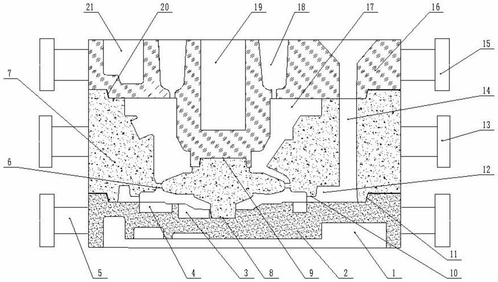
The invention relates to the technical field of sand mold casting, in particular to a 3D printing sand mold of a supercharger bearing shell and a molding method. Comprising a lower box sand mold, a middle box sand mold, an upper box sand mold, a middle box sand mold lower core head, a middle box sand mold upper core head, two lower box sand mold lifting lugs, two middle box sand mold lifting lugs, two upper box sand mold lifting lugs and three middle box sand mold process ribs, the middle box sand mold lower core head is arranged between the lower box sand mold and the middle box sand mold, the middle box sand mold upper core head is arranged between the middle box sand mold and the upper box sand mold, lower box sand mold lifting lugs are arranged on the two sides of the lower box sand mold, middle box sand mold lifting lugs are arranged on the two sides of the middle box sand mold, and upper box sand mold lifting lugs are arranged on the two sides of the upper box sand mold. By means of the structure, the production rapidness of the supercharger bearing shell is improved, and therefore the production efficiency of the supercharger bearing shell is improved.

Description

technical field [0001] The invention relates to the technical field of sand casting, in particular to a 3D printing sand mold for a supercharger bearing shell and a molding method. Background technique [0002] At present, in the production of supercharger bearing shells, the surface quality of manual molding (core) is poor, the size error is large, and there are many seams. It is time-consuming and laborious to polish the production blank. [0003] By making a wooden mold or a metal mold, pouring the raw material in the wooden mold or the metal mold, and waiting for the raw material to self-harden and form, the corresponding sand mold can be obtained. [0004] However, in the process of using wood mold or metal mold to produce supercharger bearing shell, various types and specifications of products correspond to a set of molds. Assembling, grinding, the cycle is long, and the production speed of the supercharger bearing shell is not good, thus affecting the production effi...

Claims


Application Information

Patent Timeline
IPC IPC(8): B22D15/02B33Y10/00B33Y80/00
CPCB22D15/02B33Y10/00B33Y80/00
Inventor 廖宏
Owner CHONGQING JIANGJIN SHIPBUILDING IND
Learn More