Downhole formation testing tool

a formation testing and drill string technology, applied in the field of drill hole formation testing tools, can solve the problems of borehole dimensional limitations, drilling string cannot be used to rotate the coring bit, and the drill string cannot provide the weight required

Active Publication Date: 2007-03-20
SCHLUMBERGER TECH CORP
View PDF28 Cites 98 Cited by
  • Summary
  • Abstract
  • Description
  • Claims
  • Application Information

AI Technical Summary

Benefits of technology

[0009]By contrast, in “sidewall coring,” the coring bit is extended radially from the downhole tool and advanced through the side wall of a drilled borehole. In sidewall coring, the drill string typically cannot be used to rotate the coring bit, nor can it provide the weight required to drive the bit into the formation. Instead, the coring tool itself must generate both the torque that causes the rotary motion of the coring bit and the axial force, called weight-on-bit (“WOB”), necessary to drive the coring bit into the formation. Another challenge of sidewall coring relates to the dimensional limitations of the borehole. The available space is limited by the diameter of the borehole. There must be enough space to house the devices to operate the coring bit and enough space to withdraw and store a core sample. A typical sidewall core sample is about 1.5 inches (˜3.8 cm) in diameter and less than 3 inches long (˜7.6 cm), although the sizes may vary with the size of the borehole. Examples of sidewall coring tools are shown and described in U.S. Pat. Nos. 4,714,119 and 5,667,025, both assigned to the assignee of the present invention.
[0014]In one or more embodiments, the invention related to a method for evaluating a formation that includes lowering a wireline assembly into a borehole, activating a formation testing tool connected in the wireline assembly to obtain a sample fluid from the formation, and activating a coring tool connected in the wireline assembly to obtain a core sample.
[0044]In practice, a wireline tool will generally include several different components, some of which may be comprised of two or more modules (e.g., a sample module and a pumpout module of a formation testing tool). In this disclosure, “module” is used to describe any of the separate tools or individual tool modules that may be connected in a wireline assembly. “Module” describes any part of the wireline assembly, whether the module is part of a larger tool or a separate tool by itself. It is also noted that the term “wireline tool” is sometimes used in the art to describe the entire wireline assembly, including all of the individual tools that make up the assembly. In this disclosure, the term “wireline assembly” is used to prevent any confusion with the individual tools the make up the wireline assembly (e.g., a coring tool, a formation testing tool, and an NMR tool may all be included in a single wireline assembly).
[0017]In one or more embodiments, the invention relates to a method for taking downhole samples that includes establishing fluid communication between a flowline in a downhole tool and a formation by extending the a packer seal to be in contact with a formation, obtaining a core sample using a coring bit configured to extend inside a sealing area of the packer seal, ejecting the core from the coring bit and into a sample chamber, and withdrawing a formation fluid from the formation through the flowline.
[0017]In one or more embodiments, the invention relates to a method for taking downhole samples that includes establishing fluid communication between a flowline in a downhole tool and a formation by extending the a packer seal to be in contact with a formation, obtaining a core sample using a coring bit configured to extend inside a sealing area of the packer seal, ejecting the core from the coring bit and into a sample chamber, and withdrawing a formation fluid from the formation through the flowline.

Problems solved by technology

In sidewall coring, the drill string typically cannot be used to rotate the coring bit, nor can it provide the weight required to drive the bit into the formation.
Another challenge of sidewall coring relates to the dimensional limitations of the borehole.
The available space is limited by the diameter of the borehole.
The additional steps of deploying a wireline formation testing tool, and then also deploying a wireline coring tool further delay the wellbore operations.
However, the power requirements of conventional coring tools have been incompatible with the power capabilities of existing wireline formation testers.
The electronic and power connections in a formation testing tool are generally not designed to provide the power to support a wireline sidewall coring tool.
The additional power provided by the drilling tool is currently unavailable for wireline applications.

Method used


Image

  • Downhole formation testing tool
  • Downhole formation testing tool
  • Downhole formation testing tool

Examples


Embodiment Construction

[0038]Some embodiments of the present invention relate to a wireline assembly that includes a low-power coring tool that may be connected to a formation testing tool. Other embodiments of the invention relate to a field joint that may be used to connect a coring tool to a formation testing tool. Some embodiments of the invention relate to a downhole tool that includes a combined formation testing and a coring assembly.

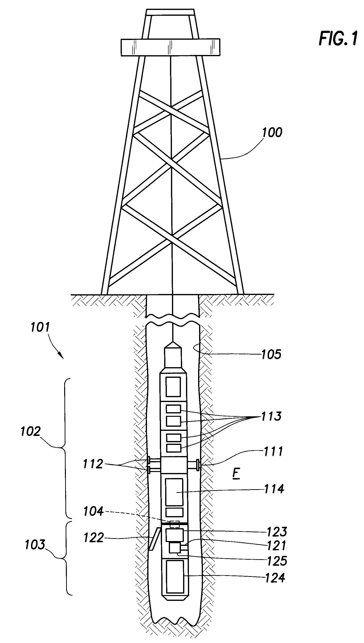
[0039]FIG. 1 shows a schematic of a wireline apparatus 101 deployed into a wellbore 105 from a rig 100 in accordance with one embodiment of the invention. The wireline apparatus 101 includes a formation testing tool 102 and a coring tool 103. The formation testing tool 102 is operatively connected to the coring tool 103 via field joint 104.

[0040]The formation testing tool 102 includes a probe 111 that may be extended from the formation testing tool 102 to be in fluid communication with a formation F. Back up pistons 112 may be included in the tool 101 to assist in push...


PUM


Abstract

Embodiments of the invention relate to a wireline assembly that includes a coring tool for taking coring samples of the formation and a formation testing tool for taking fluid samples from the formation, where the formation testing tool is operatively connected to the coring tool. In some embodiments, the wireline assembly includes a low-power coring tool. In other embodiments, the coring tool includes a flowline for formation testing.

Description

BACKGROUND OF INVENTION[0001]Wells are generally drilled into the ground to recover natural deposits of oil and gas, as well as other desirable materials, that are trapped in geological formations in the Earth's crust. A well is drilled into the ground and directed to the targeted geological location from a drilling rig at the Earth's surface.[0002]Once a formation of interest is reached, drillers often investigate the formation and its contents through the use of downhole formation evaluation tools. Some types of formation evaluation tools form part of a drill string and are used during the drilling process. These are called, for example, “logging-while-drilling” (“LWD”) tools or “measurement-while-drilling” (“MWD”) tools. Other formation evaluation tools are used sometime after the well has been drilled. Typically, these tools are lowered into a well using a wireline for electronic communication and power transmission. These tools are called “wireline” tools.[0003]One type of wire...

Claims


Application Information

Patent Timeline
Patent Type & Authority Patents(United States)
IPC IPC(8): E21B47/00E21B49/08E21BE21B25/00E21B49/00E21B49/04E21B49/06E21B49/10
CPCE21B49/04E21B49/10E21B49/06E21B49/08E21B49/082
Inventor REID, LENNOXHARRIGAN, EDWARDBRENNAN, III, WILLIAM E.
Owner SCHLUMBERGER TECH CORP
Why Eureka
Try Eureka