Thin-wall sample test fixture

A test fixture and thin-walled technology, applied in the direction of manufacturing tools, workpiece clamping devices, etc., can solve the problems of reducing data reliability, waste of resources, time, insufficient to fully reflect the high temperature mechanical characteristics of thin-walled castings, etc., to improve the experimental Accuracy, reduce the amount of deformation, improve the effect of the success rate

Pending Publication Date: 2022-07-15
北航(四川)西部国际创新港科技有限公司
View PDF0 Cites 0 Cited by
  • Summary
  • Abstract
  • Description
  • Claims
  • Application Information

AI Technical Summary

Problems solved by technology

However, the research results are not enough to fully reflect the high-temperature mechanical characteristics of cast thin-walled high-temperature alloys. As a result, the current understanding of the thin-walled service behavior and microscopic mechanism of single crystal superalloys is still not deep enough. Critical wall thickness under given conditions
[0005] Since thin-walled components need to apply less stress at the same stress level when conducting high-temperature mechanical experiments, the surface state, residual stress, and mechanical testing machine alignment of thin-walled samples are moderate compared with standard creep samples. It will have a more significant impact on the mechanical data of the sample, which not only causes a serious waste of resources and time, but also reduces the reliability of the data

Method used


Image

  • Thin-wall sample test fixture
  • Thin-wall sample test fixture
  • Thin-wall sample test fixture

Examples


Embodiment Construction

[0030] The technical solutions in the embodiments of the present invention will be clearly and completely described below with reference to the accompanying drawings in the embodiments of the present invention. Obviously, the described embodiments are only a part of the embodiments of the present invention, but not all of the embodiments. Based on the embodiments of the present invention, all other embodiments obtained by those of ordinary skill in the art without creative efforts shall fall within the protection scope of the present invention.

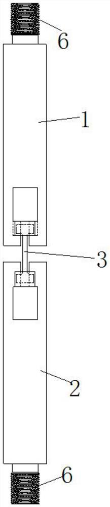
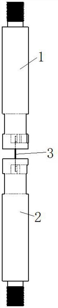
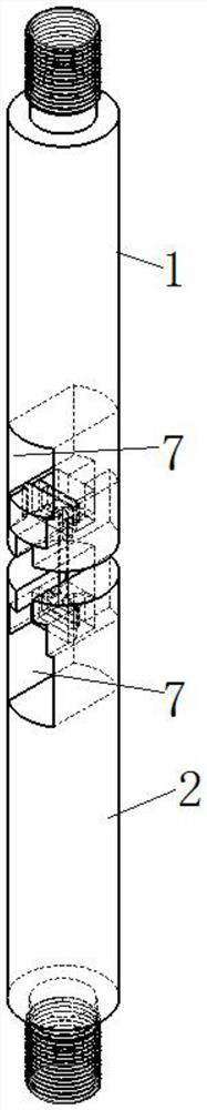
[0031] The purpose of the present invention is to provide a thin-walled sample test fixture to solve the above-mentioned problems in the prior art, which can fix the thin-walled sample to be processed on the axis of the chuck, and greatly improves the experimental accuracy.

[0032] In order to make the above objects, features and advantages of the present invention more clearly understood, the present invention will be described in fu...


PUM


Abstract

The invention discloses a thin-wall sample test fixture, and relates to the related technical field of thin-wall sample test. Comprising an upper chuck, a lower chuck and a cushion block, a threaded head is arranged at one end of the upper chuck, a square hole is formed in the side wall of the other end of the upper chuck, a square groove communicated with the square hole is formed in the side wall of the end, away from the threaded head, of the square hole, one side of the square groove is open, and the other side of the square groove is closed. The strip-shaped hole penetrates through the square groove and the closed side of the square groove and then is communicated with the square hole, and radial projections of the square hole and the square groove are symmetrically located on the two sides of the radial projection of the strip-shaped hole respectively. The lower chuck and the upper chuck have the same structure; the cushion blocks are used for fixedly abutting the two ends of the thin-wall sample penetrating through the strip-shaped holes into the square grooves of the upper chuck and the lower chuck respectively. According to the thin-wall sample test fixture provided by the invention, the thin-wall sample to be processed can be fixed at the axis of the chuck, so that the experiment accuracy is greatly improved.

Description

technical field [0001] The invention relates to the related technical field of thin-walled sample testing, in particular to a thin-walled sample testing fixture. Background technique [0002] Aero-engines are mechanical parts that rotate at high speed and high temperature. "Adjustable wide bypass ratio, wide supercharging ratio adjustment rate, and high temperature before turbine" are typical technical features of a new generation of aero-engines in the future. [0003] In order to meet the current 2100-2200K turbine front temperature design requirements, the high-pressure turbine blades adopt a "super-air cooling" structure, which significantly improves the cooling efficiency by reducing the blade thickness, designing a double-wall structure, complex inner cavity channels, and increasing air film cooling. the goal of. In the future, the temperature before the turbine of the new generation of aero-engines will be as high as 2400K, and the high-pressure turbine blades will ...

Claims


Application Information

Patent Timeline
Patent Type & Authority Applications(China)
IPC IPC(8): B25B11/00
CPCB25B11/00
Inventor 尚勇马国铨李树索张双琪赵海根裴延玲宫声凯
Owner 北航(四川)西部国际创新港科技有限公司
Why Eureka
Try Eureka