
Prefabricated assembly type component steel bar positioner

A prefabricated assembly and locator technology, which is applied in the construction field, can solve the problems of insecure connection between the template and the steel structure, the hole plug is not easy to install, and the connection is difficult, so as to achieve the effect of convenient bundling, easy disassembly and fixation, and less workload.

Pending Publication Date: 2022-07-15
SINOHYDRO BUREAU 7 CO LTD
View PDF0 Cites 0 Cited by
  • Summary
  • Abstract
  • Description
  • Claims
  • Application Information

AI Technical Summary

Problems solved by technology

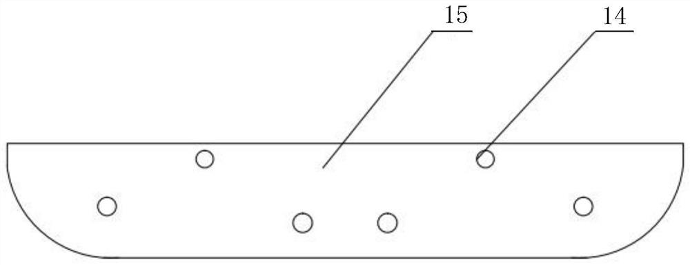
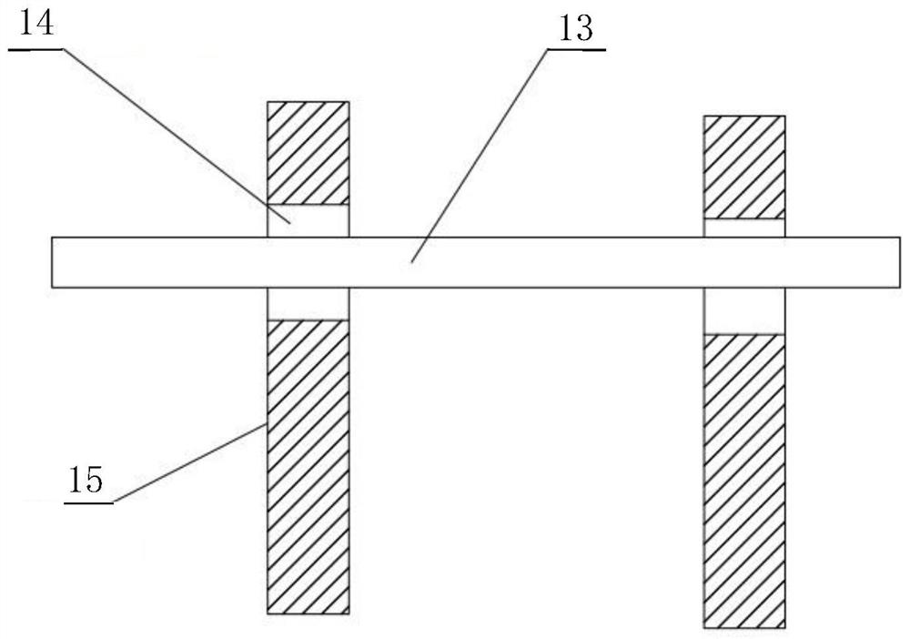
[0004] However, there are certain problems in this form, specifically as shown in the accompanying drawings figure 1 as well as figure 2 As shown, the reinforcing bar 13 is not fixedly connected with the formwork when passing through the formwork reinforcement hole 14 of the formwork 15. The formwork reinforcement hole is usually larger than the diameter of the reinforcement bar. The diameter of the reinforcement hole is several times that of the steel bar, so it will be relatively difficult to connect the steel bar to the formwork by welding. When the hole plug structure is used, not only the coaxiality between the steel bar and the formwork penetration hole is required, but also the reinforcement and the formwork. After passing through the reinforcement hole of the formwork, the hole plug is not easy to install, which leads to the unreliable connection between the formwork and the steel structure

Method used


Image

  • Prefabricated assembly type component steel bar positioner
  • Prefabricated assembly type component steel bar positioner
  • Prefabricated assembly type component steel bar positioner

Examples


Embodiment Construction

[0022] The technical solutions in the embodiments of the present invention will be clearly and completely described below with reference to the accompanying drawings in the embodiments of the present invention.

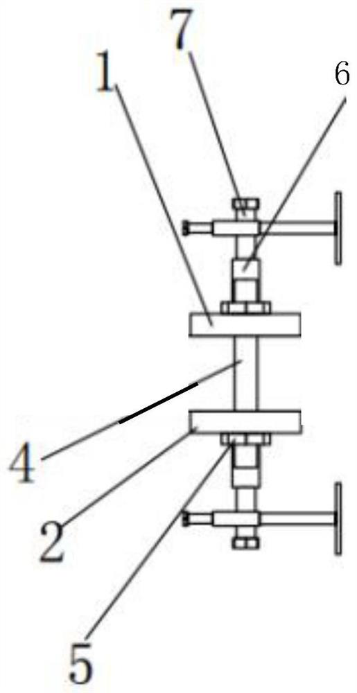
[0023] see image 3 , Figure 4 , a prefabricated component steel bar locator, the key technology of which is to include an upper clamp plate 1, a lower clamp plate 2, a lead screw 7 and a rotating sleeve 9; the left and right sides between the upper clamp plate 1 and the lower clamp plate 2 are respectively installed. The tightening screw 4 and the right clamping screw 3, the center position of the upper surface of the upper clamp plate 1 and the center position of the lower surface of the lower clamp plate 2 are fixed with a guide thread sleeve 6, and the guide thread sleeve 6 and the plate surface to which it is fixedly connected are mutually connected. Vertically, the lead screw 7 is screwed into the inner cavity of the guide threaded sleeve 6, and the lead screw...


PUM


Abstract

The invention discloses a prefabricated assembly type component steel bar positioner, and relates to the field of buildings, in particular to a prefabricated assembly type component steel bar positioning device. The device comprises an upper clamping plate, a lower clamping plate, a guide screw rod and a rotating sleeve, a left clamping screw rod and a right clamping screw rod are installed between the upper clamping plate and the lower clamping plate, guide threaded sleeves are fixed to the center of the upper surface of the upper clamping plate and the center of the lower surface of the lower clamping plate, and the guide screw rod is screwed into an inner cavity of each guide threaded sleeve. One end of the rotating sleeve is inserted into an inner push screw, the other end of the rotating sleeve is inserted into an inner push sliding rod, and the outer end of the inner push sliding rod is fixedly provided with a clinging plate. The device has the beneficial effects that the clamping plate, the lower clamping plate, the left clamping screw rod, the right clamping screw rod and the guide threaded sleeve are arranged, so that relatively inclined reinforcing steel bars can be effectively clamped; and the rotating sleeve is arranged, so that the angle and the direction of the relatively inclined reinforcing steel bars can be effectively adjusted.

Description

technical field [0001] A prefabricated component reinforcement locator relates to the field of construction, in particular to a prefabricated component reinforcement location device. Background technique [0002] Prefabricated components are relatively common building structures at present. They are bundled by formwork and steel bars, and concrete is poured and cured in the factory area, and then assembled at the building location. This assembly method is less affected by outdoor weather and is more efficient than the cast-in-place form. [0003] In the existing prefabricated assembly structure, a skeleton structure is usually formed by using a steel formwork and bundling of steel bars, and then the final molding is realized by pouring the skeleton. [0004] However, there are certain problems in this form, such as the drawings in the description. figure 1 as well as figure 2 As shown, the reinforcing bar 13 is not fixedly connected to the formwork when passing through t...

Claims


Application Information

Patent Timeline
Patent Type & Authority Applications(China)
IPC IPC(8): B28B23/02B28B7/00
CPCB28B23/024B28B7/0002
Inventor 曹辉娄彩红秦兴喜周榆翔李兵蔡伟丁华星肖海华
Owner SINOHYDRO BUREAU 7 CO LTD
Learn More