Rear cross beam assembly of motor suspension system, auxiliary frame assembly and new energy automobile
A technology of a new energy vehicle and suspension system, applied to the rear beam assembly, new energy vehicle field, can solve problems such as small scope of rear beams, and achieve the effect of good reliability
- Summary
- Abstract
- Description
- Claims
- Application Information
AI Technical Summary
Problems solved by technology
Method used
Image
Examples
Embodiment 1
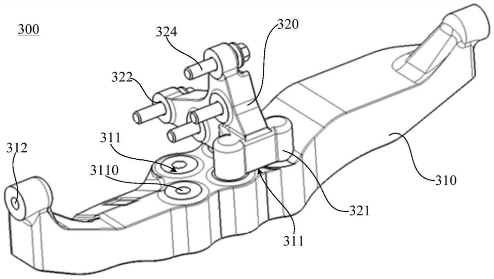
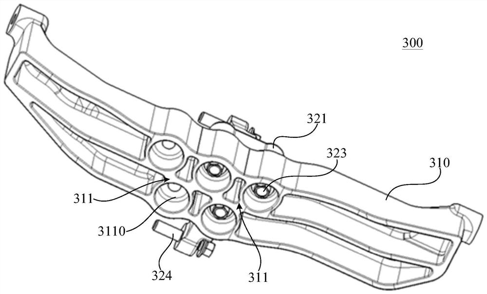
[0057] like Figure 1-Figure 2 As shown, the embodiment of the present embodiment discloses a rear cross member assembly 300 of a motor suspension system, including a rear cross member body 310 and a first connecting bracket 320; wherein, the two ends of the rear cross member body 310 are respectively connected with the suspension system. The rear left suspension 230 and the rear right suspension 240 are connected, and the rear beam body 310 is sequentially provided with at least two installation positions 311 along the length direction of the rear beam body 310 ; one end of the first connection bracket 320 is provided with each installation position 311 matching connecting portion 321, the first connecting bracket 320 is detachably connected to one of the at least two mounting positions 311 through the connecting portion 321, and is used to fix the drive assembly shell 21 of the new energy vehicle (see Figure 4 ).
[0058] It should be noted that the rear cross member assem...
Embodiment 2
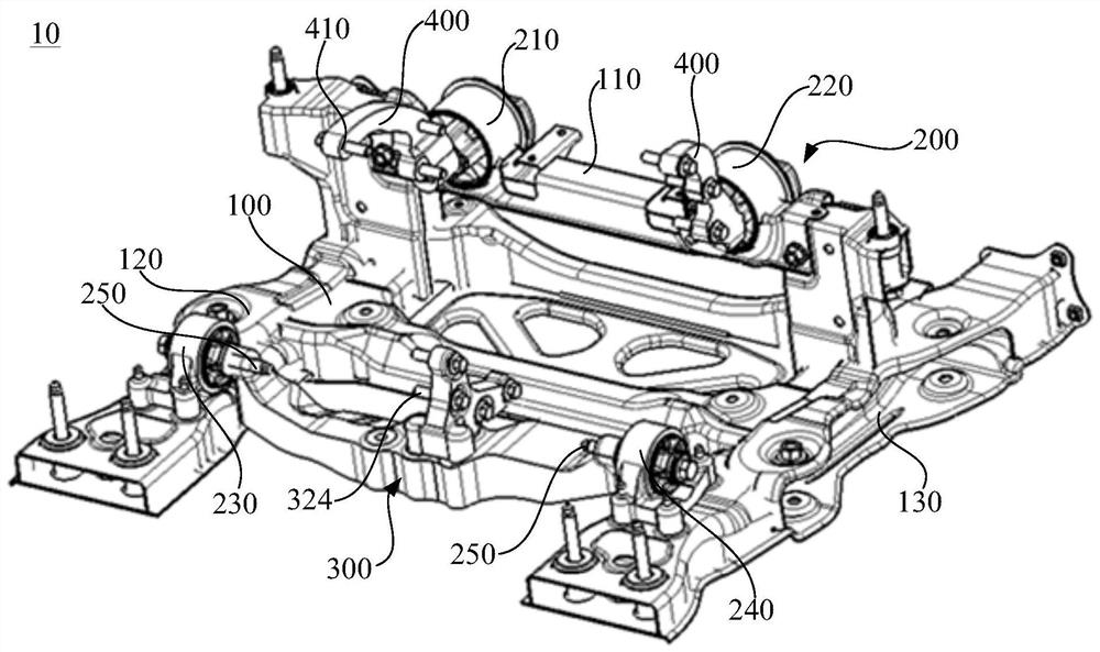
[0079] like image 3 As shown, this embodiment provides a sub-frame assembly 10, including a sub-frame 100 and a suspension assembly 200, the suspension assembly 200 is mounted on the sub-frame 100; it also includes the rear cross member assembly in Embodiment 1 300.
[0080] Specifically, in this embodiment, the suspension assembly 200 includes a front left suspension 210 and a front right suspension 220 disposed on the upper beam 110 of the middle tower of the subframe 100 , and a left suspension 220 respectively disposed on the subframe 100 The rear left suspension 230 and the rear right suspension 240 on the longitudinal beam 120 and the right longitudinal beam 130; the front left suspension 210 and the front right suspension 220 are respectively used to fix the drive assembly shell 21 of the new energy vehicle (see Figure 4 ), the two ends of the rear cross member body 310 are respectively fixed and detachably connected to the rear left suspension 230 and the rear right...
Embodiment 3
[0093] This embodiment provides a new energy vehicle, such as Figure 4-Figure 5 As shown, a drive assembly 20 is included, which has a drive assembly housing 21, and also includes the subframe assembly 10 of the second embodiment.
[0094] Specifically, the drive assembly housing 21 has a front part 22 and a rear part 23, and two ends of the front part 22 of the drive assembly housing 21 are respectively fixed and detachable to the other ends of the two second connection brackets 400; The body 310 is located between the sub-frame 100 and the drive assembly casing 21, and is closer to the front of the new energy vehicle than the rear 23 of the drive assembly casing 21 in the length direction of the new energy vehicle; the drive assembly casing The position of the bottom of the 21 close to the rear 23 is fixed and detachable to the other end of the first connecting bracket 320 .
[0095] It should be noted that the front portion 22 of the drive assembly housing 21 refers to a ...
PUM
 Abstract
Description
Claims
Application Information
 - R&D
- Intellectual Property
- Life Sciences
- Materials
- Tech Scout
- Unparalleled Data Quality
- Higher Quality Content
- 60% Fewer Hallucinations
Browse by: Latest US Patents, China's latest patents, Technical Efficacy Thesaurus, Application Domain, Technology Topic, Popular Technical Reports.
© 2025 PatSnap. All rights reserved.Legal|Privacy policy|Modern Slavery Act Transparency Statement|Sitemap|About US| Contact US: help@patsnap.com


