
Water drainage pipeline sludge organic and inorganic component on-line separation carbon source extraction system and method

A technology of inorganic components and drainage pipes, applied in separation methods, water/sludge/sewage treatment, water pollutants, etc., can solve the problem of difficult land selection for centralized sludge treatment stations, large transportation workload, and non-point source pollution. and other problems, to achieve the effect of high utilization rate of sludge resources, improvement of filtration flux, and reduction of carbon emissions

Active Publication Date: 2022-07-15
NORTH CHINA MUNICIPAL ENG DESIGN & RES INST
View PDF8 Cites 0 Cited by
  • Summary
  • Abstract
  • Description
  • Claims
  • Application Information

AI Technical Summary

Problems solved by technology

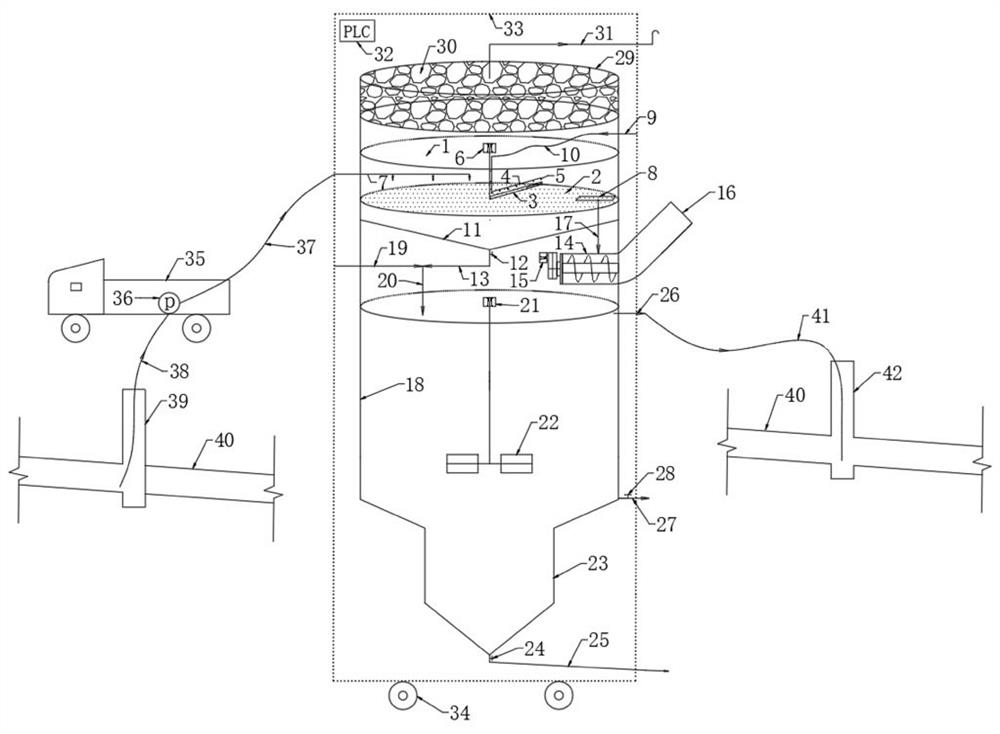
[0005] The purpose of the present invention is to overcome the deficiencies in the prior art, and provide a system and method for the online separation of organic and inorganic components of drainage pipe sludge and carbon source extraction system. The on-line and on-site rapid treatment of dredging sludge in the drainage pipe network can solve the common problem of CO generation in the centralized treatment and disposal of dredging sludge in the existing urban drainage pipe network. 2 、CH 4 Practical problems such as greenhouse gases, large amount of dredging sludge transportation workload, non-point source pollution caused by sludge running, dripping and leaking during transportation, difficulty in selecting construction land for centralized sludge treatment station, etc.

Method used


Image

  • Water drainage pipeline sludge organic and inorganic component on-line separation carbon source extraction system and method
  • Water drainage pipeline sludge organic and inorganic component on-line separation carbon source extraction system and method
  • Water drainage pipeline sludge organic and inorganic component on-line separation carbon source extraction system and method

Examples


Embodiment 1

[0078] A method for extracting carbon source by on-line separation of organic and inorganic components of drainage pipeline sludge, utilizing the above-mentioned system for on-line separation of carbon source extraction from organic and inorganic components of drainage pipeline sludge for extraction, comprising the following steps:

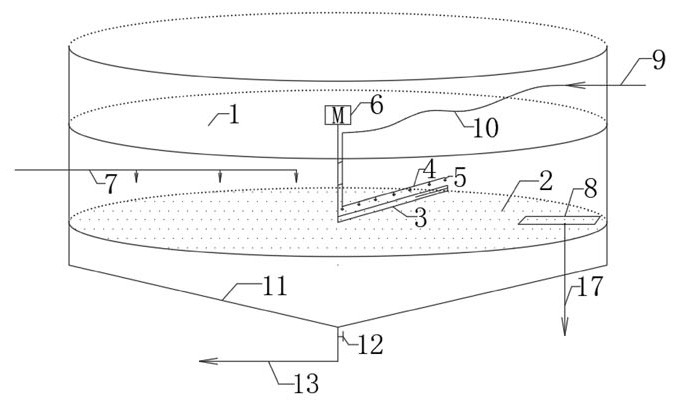
[0079] a. Use the suction pump 36 of the sludge cleaning vehicle 35 in the drainage pipe network to pump the dredged sludge in the drainage pipe network to the mud distribution pipe 7 of the pre-treatment module 1 through the suction pipe 38 and the pressure mud pipe 37 In the middle, under the continuous push of the rotating scraper 3 with a height of 4cm, the mud distribution pipe 7 distributes the mud on the surface of the screen grid 2, and most of the sludge quickly passes through the horizontally arranged circular screen under the action of gravity. The circular mesh with an inner diameter of 3 mm of the grid 2 enters the conical rectifying m...

Embodiment 2

[0085] A method for on-line separation of carbon source extraction from organic and inorganic components of sludge in a drainage pipeline, comprising the following steps:

[0086] a. Use the suction pump 36 of the drainage pipe network sludge cleaning vehicle 35 to pump the dredged sludge in the drainage pipe network 40 to the sludge distribution pipe of the pre-treatment module 1 through the sludge suction pipe 38 and the pressure sludge discharge pipe 37 7. Under the continuous push of the rotating scraper 3 with a height of 4cm, the mud distribution pipe 7 distributes mud on the surface of the fixed circular mesh grille 2, and most of the mud quickly passes through the horizontally arranged circle under the action of gravity. The circular mesh holes with an inner diameter of 2 mm of the mesh mesh grid 2 enter the conical rectifying mud hopper 11 at the lower part of the mesh plate grid 2, and at the same time the large-sized particles in the dredging sludge are trapped on th...

Embodiment 3

[0092] A method for on-line separation of carbon source extraction from organic and inorganic components of sludge in a drainage pipeline, comprising the following steps:

[0093] a. Use the suction pump 36 of the drainage pipe network sludge cleaning vehicle 35 to pump the dredged sludge in the drainage pipe network 40 to the sludge distribution pipe of the pre-treatment module 1 through the sludge suction pipe 38 and the pressure sludge discharge pipe 37 7. Under the continuous push of the rotating scraper 3 with a height of 4cm, the mud distribution pipe 7 distributes mud on the surface of the fixed circular mesh grille 2, and most of the mud quickly passes through the horizontally arranged circle under the action of gravity. The circular mesh holes with an inner diameter of 2.5 mm of the mesh mesh grid 2 enter the conical rectifying mud hopper 11 at the lower part of the mesh plate grid 2, and at the same time, the large-sized particles in the dredging sludge are trapped on...


PUM


Abstract

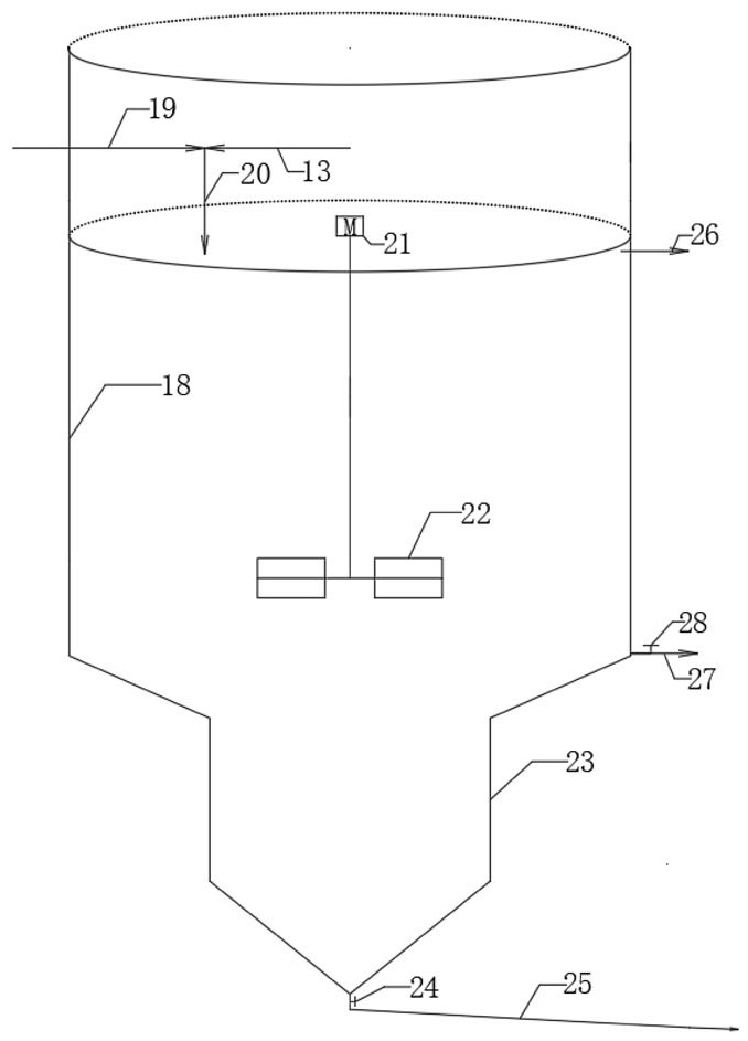
The invention relates to a drainage pipeline sludge organic and inorganic component online separation carbon source extraction system and method.The extraction system comprises a system outer box, a system body is arranged in the system outer box, and the system body sequentially comprises a deodorization module, a pretreatment module and a cyclone separation module which are spliced together from top to bottom; a grid residue squeezing module is arranged on the side wall of the upper part of the cyclone separation module, and the pretreatment module, the cyclone separation module and the grid residue squeezing module are electrically connected with the control module respectively. A drainage pipeline sludge organic and inorganic component on-line separation carbon source extraction system is adopted to carry out on-line on-site rapid treatment on dredging sludge of a drainage pipeline network; the practical problems that greenhouse gases such as CO2 and CH4 are generated, the transportation workload of a large amount of desilted sludge is large, non-point source pollution is generated due to leakage of the sludge in the transportation process, and construction land of a centralized sludge treatment station is difficult to select in an existing centralized treatment and disposal method for desilted sludge of an urban drainage pipe network can be solved.

Description

technical field [0001] The invention belongs to the technical field of drainage, and in particular relates to a carbon source extraction system and method for on-line separation of organic and inorganic components of sludge in a drainage pipeline. Background technique [0002] Different from developed countries such as Europe and the United States, my country's urban sewage collection pipe network generally has practical operation problems such as high water level and low flow rate, which lead to the deposition of a large amount of particulate organic matter in the sewage. , is the main reason for the low rate of centralized collection of urban domestic sewage in my country. According to statistics, the national average centralized collection rate of sewage in 2020 is only 64%, and only 20%-30% in many cities. The sludge deposited in the pipe network will also affect the efficiency of sewage collection and produce a large amount of CH anaerobic. 4 and other greenhouse gases,...

Claims


Application Information

Patent Timeline
IPC IPC(8): C02F11/121B01D53/04C02F11/00C02F101/10
CPCC02F11/121C02F11/00B01D53/04C02F2101/105B01D2257/304Y02P20/10C02F1/283C02F1/38C02F2303/16C02F9/00C02F11/122C02F11/127C02F2201/005C02F2303/02C02F2303/24
Inventor 孙永利郑兴灿李鹏峰杨敏隋克俭
Owner NORTH CHINA MUNICIPAL ENG DESIGN & RES INST
Learn More