Water recession and desilting structure of silt-laden channel

A channel and water receding technology, which is applied in artificial waterways, water conservancy projects, irrigation pipelines, etc., can solve the problems of not considering the problem of sediment deposition, and cannot solve the problem of long-distance channel deposition, and achieve the effect of reducing the cement and sand content of the channel

Pending Publication Date: 2022-07-15
POWERCHINA XIBEI ENG
View PDF0 Cites 0 Cited by
  • Summary
  • Abstract
  • Description
  • Claims
  • Application Information

AI Technical Summary

Problems solved by technology

None of the above considerations considers the problem of sediment deposition on plain sediment-rich channels. The setting of r

Method used


Image

  • Water recession and desilting structure of silt-laden channel
  • Water recession and desilting structure of silt-laden channel
  • Water recession and desilting structure of silt-laden channel

Examples


Example Embodiment

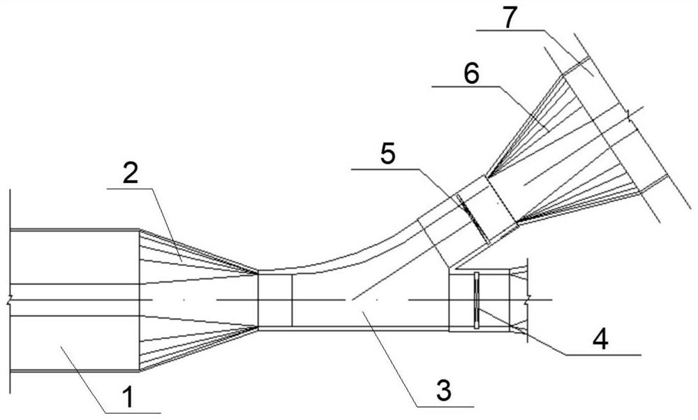
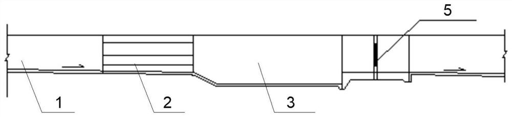
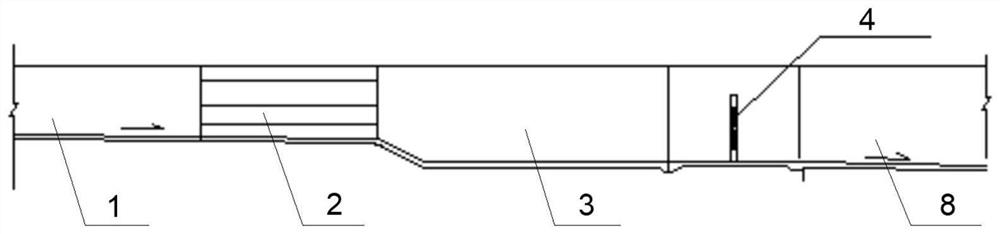
[0023] The present invention will be specifically described below in conjunction with the accompanying drawings, such as Figure 1 to Figure 3 , the present invention provides a technical solution: a water and sediment discharge structure with multiple sediment channels, including an upstream channel 1, a downstream channel 7, a water and sediment discharge gate 4 and a control gate 5; the upstream channel 1 and the downstream channel 7 pass through For the connection of the curve, set the backwater and sand discharge gate 4 on the concave bank of the curve, and set the control gate 5 on the straight section of the convex bank of the curve. When irrigating water, open the control gate 5, and close the backwater and sand discharge gate 4; when the sand needs to be discharged after the irrigation, close the control gate 5 and open the backwater and sand discharge gate 4.

[0024] The upstream gradual change section 2 is connected between the upstream channel 1 and the bend. The ...


PUM


Abstract

The invention discloses a recession and desilting structure of a silt-laden channel. The recession and desilting structure comprises an upstream channel, a downstream channel, a recession and desilting channel, a desilting basin, a check gate and a recession and desilting gate. The upstream channel and the downstream channel are connected through a bend, the bend serves as a desilting basin, by means of the principle of forward sand flushing and bend water taking, the downstream channel is connected to a bend convex bank, the water recession and desilting channel is connected to a bend concave bank, and a water recession and desilting gate and a check gate are arranged at inlets of the water recession and desilting channel and the downstream channel respectively. During irrigation, the check gate is opened, the water-recession sand-discharging gate is closed, water flows through the curve, and sand and stones are deposited in the sand basin due to inertia; during sand discharging, the check gate is closed, the water-recession sand discharging gate is opened, the water flow of the water-recession sand discharging channel is increased, and overflowing sand pulling is increased through the channel, so that silt deposited in the channel is discharged.

Description

technical field [0001] The invention belongs to the field of water conservancy engineering, and relates to a water-regression and sand-removal structure for channels with many sediments. Background technique [0002] At present, among domestic irrigation channels, it is a conventional design idea to design a drainage channel to discharge excess water to ensure the safety of the channel during the flood period. In the existing design schemes, the drainage channel often adopts side weir drainage, and the side weir is often open. Type wide-top weir, or add gates to increase the overflow depth of the drainage channel and increase the overflow capacity. None of the above considerations have considered the problem of sediment deposition on the channels with many sediments in the plain. The setting of the backwater channels is mainly to discharge excess water and cannot solve the problem of deposition in long-distance channels. SUMMARY OF THE INVENTION [0003] In view of the de...

Claims


Application Information

Patent Timeline
IPC IPC(8): E02B5/00E02B5/08E02B13/00
CPCE02B5/00E02B5/08E02B13/00
Inventor 周恒任苇鲁志峰王丹迪杨继超
Owner POWERCHINA XIBEI ENG
Why Eureka
Try Eureka