
Material damage detection method and system based on image fusion, terminal and medium

A technology of material damage and image fusion, applied in image analysis, image enhancement, image data processing, etc.

Pending Publication Date: 2022-07-15
UNIV OF ELECTRONICS SCI & TECH OF CHINA
View PDF5 Cites 0 Cited by
  • Summary
  • Abstract
  • Description
  • Claims
  • Application Information

AI Technical Summary

Problems solved by technology

[0005] In order to solve the deficiencies in the prior art, the purpose of the present invention is to provide a material damage detection method, system, terminal and medium based on image fusion, not only to accurately detect a single type of defect, but also to integrate images representing different defects , and finally obtain a fusion image that can represent multiple types of defects at the same time, and realize the complete detection of the damaged part when the material surface is damaged

Method used


Image

  • Material damage detection method and system based on image fusion, terminal and medium
  • Material damage detection method and system based on image fusion, terminal and medium
  • Material damage detection method and system based on image fusion, terminal and medium

Examples


Embodiment 1

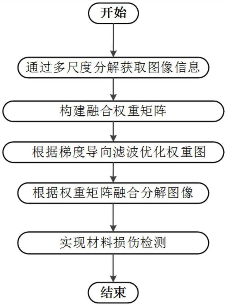
[0059] Example 1: Material damage detection method based on image fusion, such as figure 1 shown, including the following steps:

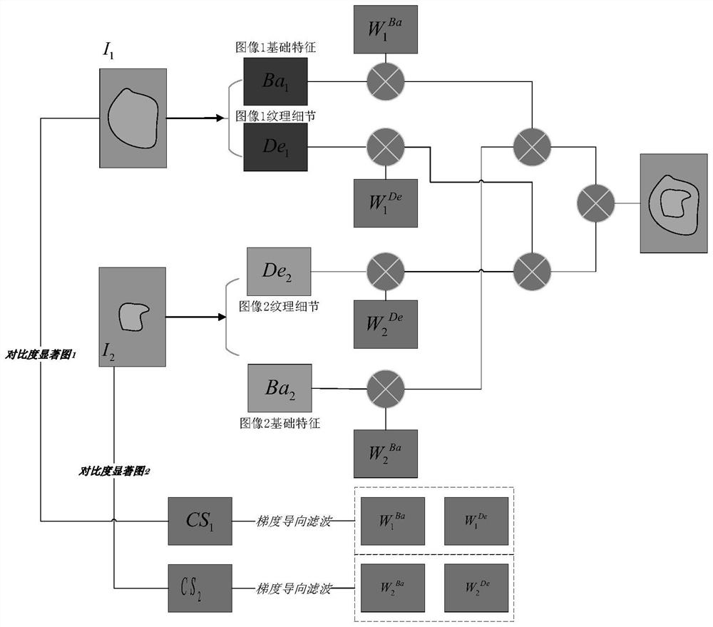
[0060] S1: Acquire two infrared damage images, and decompose the corresponding basic features and texture details from different infrared damage images through a multi-scale decomposition algorithm; it should be noted that the number of infrared damage images can also be more than two. Restricted;

[0061] S2: construct a corresponding contrast saliency map according to the contrast information in the infrared damage image, and construct a fusion weight map according to the contrast saliency map;

[0062] S3: Optimize the fusion weight map according to gradient-directed filtering, and obtain a fusion weight matrix including basic feature weights and texture detail weights;

[0063] S4: weight the basic features and texture details in different infrared damage images respectively according to all the fusion weight matrices to obtain the correspond...

Embodiment 2

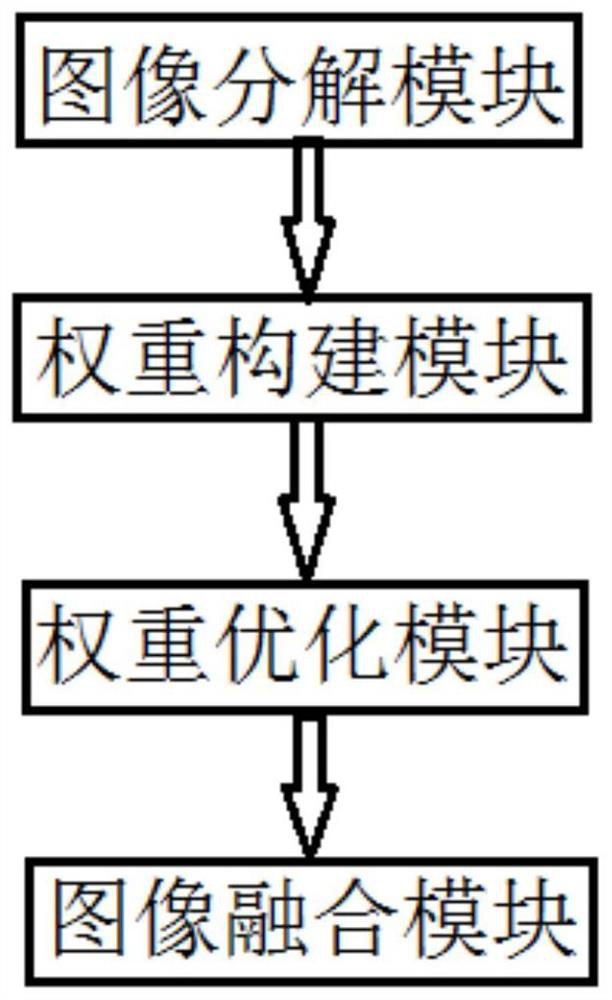
[0114] Example 2: A material damage detection system based on image fusion, the system is used for the detection method described in Example 1, such as image 3 As shown, it includes an image decomposition module, a weight building module, a weight optimization module, and an image fusion module.

[0115] Among them, the image decomposition module is used to obtain at least two infrared damage images, and decompose the corresponding basic features and texture details from different infrared damage images through a multi-scale decomposition algorithm; The corresponding contrast saliency map is constructed according to the contrast information, and the fusion weight map is constructed according to the contrast saliency map; the weight optimization module is used to optimize the fusion weight map according to the gradient-directed filtering, and obtain the fusion weight matrix including the basic feature weight and texture detail weight; image The fusion module is used to weight ...


PUM


Abstract

The invention discloses a material damage detection method and system based on image fusion, a terminal and a medium, and relates to the field of material damage detection.According to the technical scheme, the method is characterized in that infrared damage images are obtained, and corresponding basic features and texture details are obtained through decomposition from different infrared damage images through a multi-scale decomposition algorithm; constructing a corresponding contrast saliency map according to contrast information in the infrared damage image, and constructing a fusion weight map according to the contrast saliency map; optimizing the fusion weight map according to gradient guided filtering to obtain a fusion weight matrix containing basic feature weights and texture detail weights; and according to all the fusion weight matrixes, weighting the basic features and texture details in different infrared damage images to obtain corresponding basic feature maps and texture detail maps, and fusing the basic feature maps and the texture detail maps to obtain a fused image. According to the method, the fused image representing various types of defects at the same time can be obtained, and complete detection of a damaged part is realized under the condition that the surface of the material is damaged.

Description

technical field [0001] The invention relates to the field of material damage detection, and more particularly, to a material damage detection method, system, terminal and medium based on image fusion. Background technique [0002] In recent years, more and more rockets, satellites and probes have been launched into space. The collision or explosion of these objects produces a large amount of space debris of various sizes and shapes. Space debris travels through space at extremely high speeds. Due to the huge amount of debris and the inability of ground-based radar and other equipment to track effectively, hypervelocity impact of tiny space debris is inevitable, which is one of the main causes of material and structural damage to spacecraft during orbital operation. Therefore, all kinds of spacecraft exposed to the space debris environment need to be damaged. Due to the randomness of the impact event, the parameters such as the impact position and speed are unpredictable, ...

Claims


Application Information

Patent Timeline
Patent Type & Authority Applications(China)
IPC IPC(8): G06T7/00G06T5/50
CPCG06T7/0004G06T5/50G06T2207/10048G06T2207/20221G06T2207/30108
Inventor 孙志刚
Owner UNIV OF ELECTRONICS SCI & TECH OF CHINA
Learn More