
Self-adaptive valve clamping device and valve clamping system

An adaptive valve technology, applied in the direction of the heart valve, can solve the problems affecting the closing of the forceps arm and the damage of the valve leaflet, so as to achieve the effect of axial force balance and avoid damage

Pending Publication Date: 2022-07-19
HANGZHOU VALGEN MEDTECH CO LTD
View PDF0 Cites 0 Cited by
  • Summary
  • Abstract
  • Description
  • Claims
  • Application Information

AI Technical Summary

Problems solved by technology

When the valve leaflet is grasped by the forceps arm, part of the valve leaflet will fill and accumulate in the space, thus affecting the closing of the forceps arm
At the same time, if the filling of the valve leaflets cannot be detected in time through medical imaging, when the operator forcibly closes the clamping device, the forceps arm will cause damage to the valve leaflets at the place

Method used


Image

  • Self-adaptive valve clamping device and valve clamping system
  • Self-adaptive valve clamping device and valve clamping system
  • Self-adaptive valve clamping device and valve clamping system

Examples


Embodiment 1

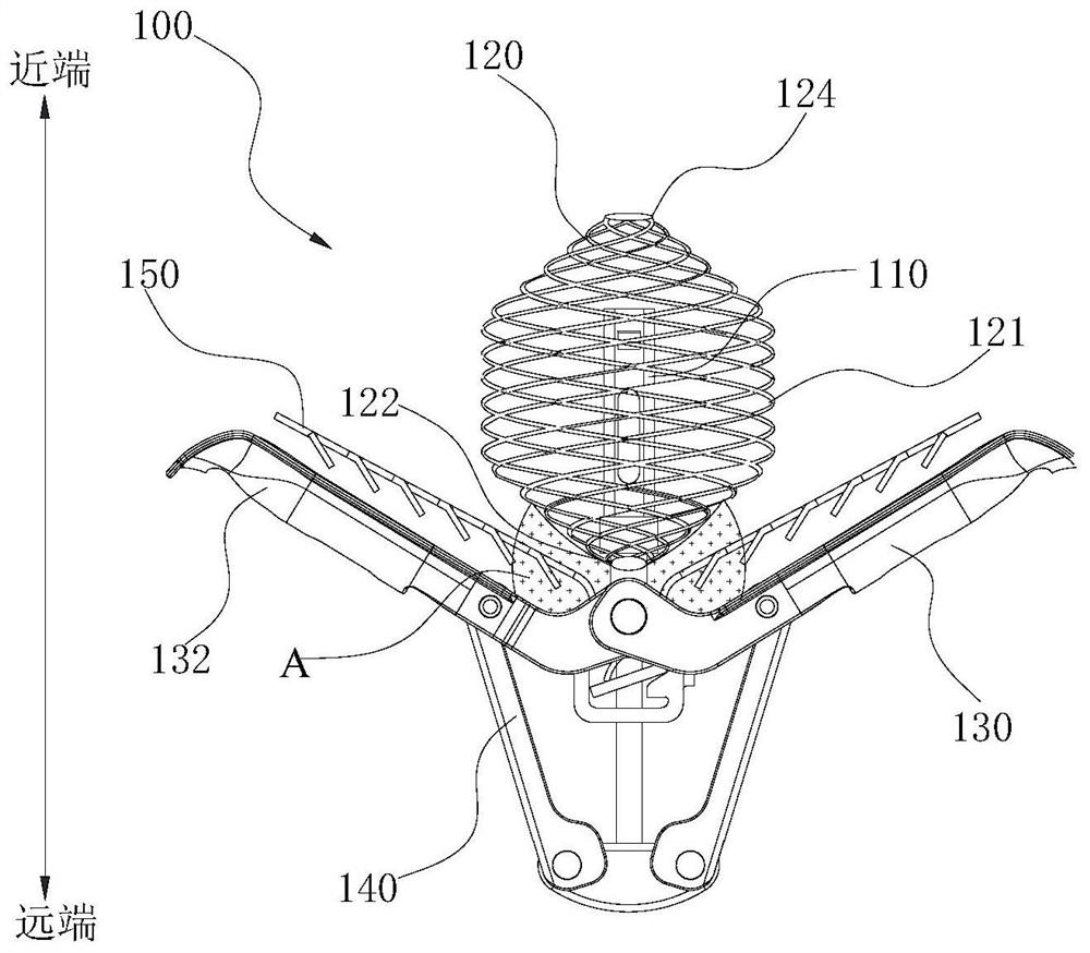
[0044] see Figure 3 to Figure 5 , An adaptive valve clamping device 100 provided in the first embodiment of the present application can be used for edge-to-edge repair of the mitral valve or tricuspid valve to treat mitral valve regurgitation or tricuspid valve regurgitation. In order to ensure the safety of the adaptive valve clamping device 100 after implantation, the adaptive valve clamping device 100 is entirely made of biocompatible materials. The following will take the adaptive valve clamping device 100 for mitral valve edge-to-edge repair as an example for detailed description. The operator uses the delivery device 200 to advance the adaptive valve clamping device 100 to the patient's mitral valve, and then operates the adaptive valve clamping device 100 remotely to clamp the anterior and posterior leaflets of the mitral valve together. When the leaflets of the mitral valve are aligned edge-to-edge, the operator can release the connection between the delivery device ...

Embodiment 2

[0093] see Figure 22-Figure 25 , compared with the adaptive valve clamping device 100 of the first embodiment, the adaptive valve clamping device of the second embodiment of the present application is different in that the first sealing head 426 of the adjusting part 420 and the second seat body 414 of the supporting part 410 The structure is different.

[0094] Specifically, the first head 426 is movably sleeved on the outer side of the second seat body 414 of the support portion 410 , the inner cavity of the first head 426 is provided with a first anti-rotation member 4260 , and the outer surface of the second seat body 414 corresponds to The first anti-rotation member 4260 is provided with a second anti-rotation member 4140, and the first anti-rotation member 4260 and the second anti-rotation member 4140 are detachably connected to each other. In this way, the adjusting portion 420 is restricted from rotating around the axial direction by arranging the first anti-rotation...

Embodiment 3

[0101] see Figure 26 and Figure 27 , compared with the adaptive valve clamping device of the third embodiment of the present application and the adaptive valve clamping device of the second embodiment, the difference lies in the structure of the first head 526 of the adjustment part 520 and the second seat body 514 of the support part 510 different. In this embodiment, the first head 526 and the first anti-rotation member 5260 are connected separately, and / or, the second base 524 and the second anti-rotation member 5140 are connected separately. Specifically, the first head 526 and the first anti-rotation member 5260 can be fixed together by common detachable or non-detachable connection methods such as welding, bonding, screw connection, crimping, and bolt locking. The second base body 514 and the second anti-rotation member 5140 can be fixed together by common detachable or non-detachable connection methods such as welding, bonding, screw connection, crimping, bolt locki...


PUM


Abstract

The invention discloses a self-adaptive valve clamping device and a valve clamping system. The self-adaptive valve clamping device comprises a supporting part, a hollow adjusting part and a clamping part. The supporting part comprises a first seat body and a second seat body. The first seat body is arranged in the adjusting part. The adjusting part comprises a first end and a second end which are opposite, and a self-expanding body located between the first end and the second end. The first end is movably sleeved on the outer side of the second seat body and can move along the axial direction relative to the second seat body, and the second end is suspended. The first seat body is closer to the second end of the adjusting part than the second seat body. The clamping part comprises at least two clamp arms, each clamp arm is rotationally connected to the supporting part, the rotationally-connected portion of the clamp arms is close to the first end of the adjusting part, and the clamp arms rotate around the supporting part so as to be close to or away from the adjusting part. According to the self-adaptive valve clamping device, the space, close to the adjusting part, of the rotationally-connected part of the clamp arms can be enlarged, the adjusting part can better adapt to deformation of valve leaflets, and damage to the valve leaflets at the adjusting part is avoided.

Description

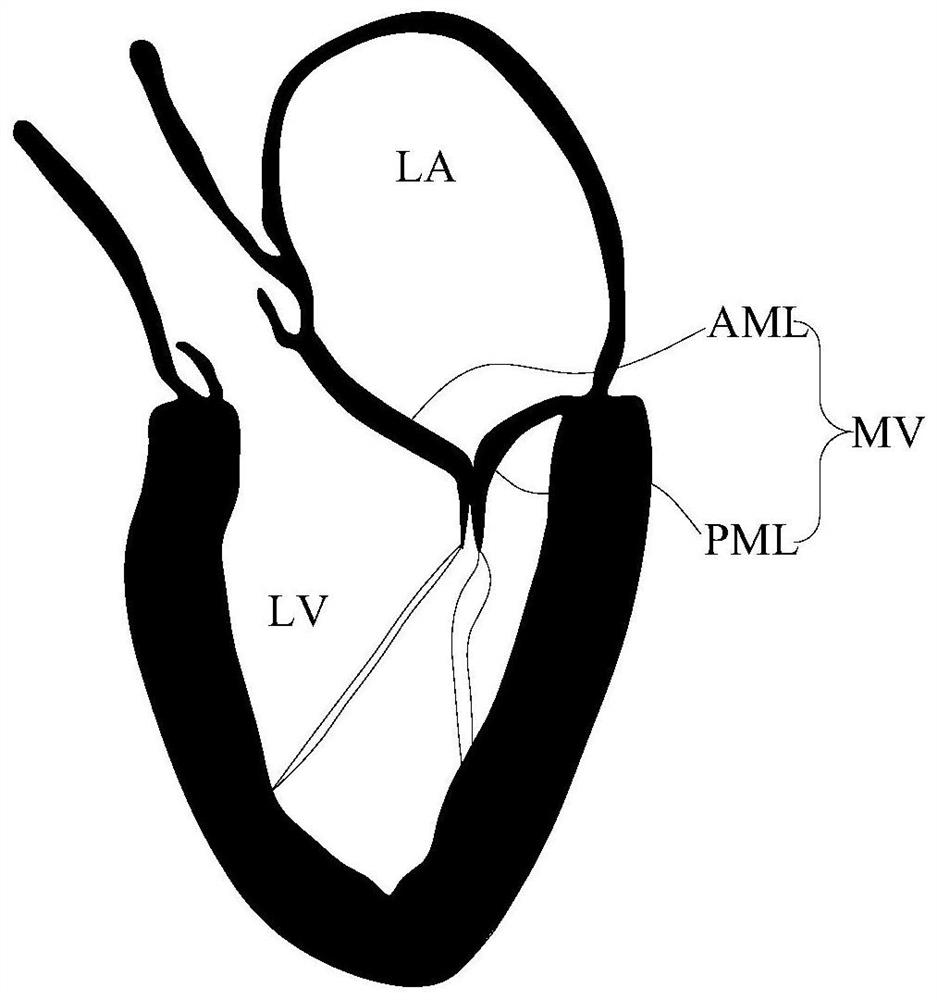
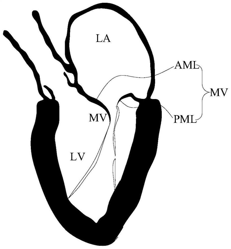
technical field [0001] The present application relates to the technical field of implanted medical devices, and in particular, to an adaptive valve clamping device and a valve clamping system including the adaptive valve clamping device. Background technique [0002] see figure 1 , The mitral valve MV is a one-way valve located between the left atrium LA and the left ventricle LV of the heart. A normal and healthy mitral valve MV can control the flow of blood from the left atrium LA to the left ventricle LV, while avoiding the flow of blood from the left ventricle LV. to the left atrium LA. The mitral valve MV consists of a pair of leaflets, called anterior leaflet AML and posterior leaflet PML. Anterior lobe AML and posterior lobe PML were fixed to the papillary muscle of left ventricular LV by chordae tendineae. Under normal circumstances, when the left ventricle of the heart LV contracts, the edges of the anterior AML and posterior PML completely coincide, preventing b...

Claims


Application Information

Patent Timeline
Patent Type & Authority Applications(China)
IPC IPC(8): A61F2/24
CPCA61F2/2466A61F2/246A61F2/2442
Inventor 张庭超张伟伟王泽涛郑贤章
Owner HANGZHOU VALGEN MEDTECH CO LTD
Learn More