Vehicle and light emitting body control device

A technology for illuminants and vehicles, applied in battery/fuel cell control devices, signaling devices, vehicle components, etc., can solve the problems of reducing the brightness of illuminants and achieve good visual recognition

Pending Publication Date: 2022-07-19
HONDA MOTOR CO LTD
View PDF1 Cites 0 Cited by
  • Summary
  • Abstract
  • Description
  • Claims
  • Application Information

AI Technical Summary

Problems solved by technology

In addition, the following technology is known: for example, in a illuminant such as a backlight of a mobile information terminal, an illuminance sensor is provided near the illuminant, and w

Method used


Image

  • Vehicle and light emitting body control device
  • Vehicle and light emitting body control device
  • Vehicle and light emitting body control device

Examples


Example

[0035] [First Embodiment]

[0036]

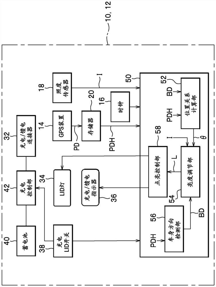
[0037] figure 1 It is a block diagram of the main part of the vehicle 10 which concerns on preferable 1st Embodiment.

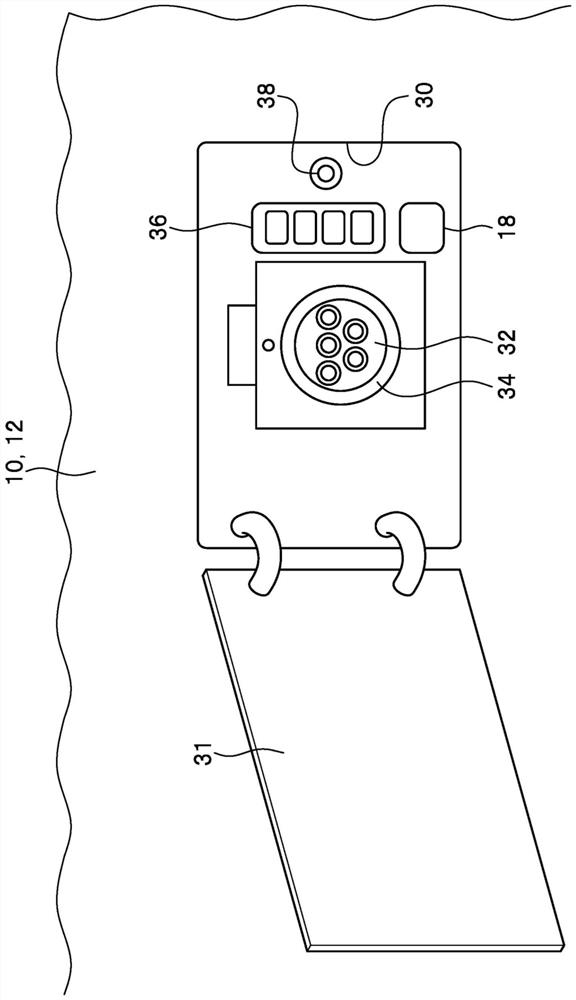
[0038] The vehicle 10 includes a vehicle body 12 covering the entire vehicle 10 , a battery 40 , a charging control portion 42 , and a charging / feeding connector 32 (power supply connection portion). The charging / feeding connector 32 is attached to the vehicle body 12 and is connected to an external power feeding device (not shown). The charging control unit 42 charges the storage battery 40 using the electric power supplied from the power feeding device.

[0039] Further, the vehicle 10 includes a LID lamp 34 (illuminator), a charging / feeding indicator 36 (illuminator), and a charging LID switch 38 . The LID light 34 illuminates the charging / feeding connector 32 . The charge / feed indicator 36 shows the charge level of the battery 40 in segments. The charging LID switch 38 is a switch that instructs the charging con...


PUM


Abstract

The invention provides a vehicle and a light emitting body control device which can realize good visibility for a light emitting body. A vehicle (10) is provided with: a vehicle body (12); a power supply connection unit (32) which is provided at a predetermined location of the vehicle body (12) and which can be connected to an external power supply device; light emitting bodies (34, 36) provided on the vehicle body (12) in proximity to the power supply connection unit (32); a position information acquisition unit (14) that acquires position information (PD) indicating the position of the vehicle body (12); a positional relationship calculation unit (52) that calculates the positional relationship between the incident axis of the sunlight and the light-emitting bodies (34, 36) on the basis of the positional information (PD) and the current date and time; and a brightness adjustment unit (54) that sets the brightness (L) of the light-emitting bodies (34, 36) on the basis of the positional relationship.

Description

technical field [0001] The present invention relates to a vehicle and a light-emitting body control device. Background technique [0002] In an electric vehicle, a plug-in hybrid vehicle, or the like, a charging LID (charging port) for charging the battery is provided. In addition, the following Patent Document 1 describes a technique in which a charging / feeding indicator formed by arranging a plurality of light-emitting bodies is provided in the vicinity of the charging LID to display the charging rate of the battery. In addition, in order to improve the visibility of the charging LID at night or the like, there is known a technique in which a circular light-emitting body is provided around the charging LID. In addition, a technique is known in which an illuminant such as a backlight of a mobile information terminal is provided with an illuminance sensor in the vicinity of the illuminant, and when the detected illuminance is high, the brightness of the illuminant is increa...

Claims


Application Information

Patent Timeline
IPC IPC(8): B60Q1/26B60L58/10B60L53/16
CPCB60Q1/2661B60L58/10B60L53/16
Inventor 前田刚宏中野和男久米泰尚佐藤玲
Owner HONDA MOTOR CO LTD
Why Eureka
Try Eureka