[0039] In order to make the purposes, technical solutions and advantages of the embodiments of the present invention clearer, the technical solutions in the embodiments of the present invention will be clearly and completely described below with reference to the accompanying drawings in the embodiments of the present invention. Obviously, the described embodiments These are some embodiments of the present invention, but not all embodiments. The components of the embodiments of the invention generally described and illustrated in the drawings herein may be arranged and designed in a variety of different configurations.
[0040] Thus, the following detailed description of the embodiments of the invention provided in the accompanying drawings are not intended to limit the scope of the invention as claimed, but are merely representative of selected embodiments of the invention. Based on the embodiments of the present invention, all other embodiments obtained by those of ordinary skill in the art without creative efforts shall fall within the protection scope of the present invention.
[0041] It should be noted that like numerals and letters refer to like items in the following figures, so once an item is defined in one figure, it does not require further definition and explanation in subsequent figures.
[0042] In the description of the present invention, it should be noted that the terms "center", "upper", "lower", "left", "right", "vertical", "horizontal", "inner", "outer", etc. The indicated orientation or positional relationship is based on the orientation or positional relationship shown in the accompanying drawings, or the orientation or positional relationship that the product of the invention is usually placed in use, only for the convenience of describing the present invention and simplifying the description, rather than indicating or implying The device or element referred to must have a particular orientation, be constructed and operate in a particular orientation, and therefore should not be construed as limiting the invention. Furthermore, the terms "first", "second", "third", etc. are only used to differentiate the description and should not be construed to indicate or imply relative importance.
[0043] Furthermore, the terms "horizontal", "vertical", "overhanging" etc. do not imply that a component is required to be absolutely horizontal or overhang, but rather may be slightly inclined. For example, "horizontal" only means that its direction is more horizontal than "vertical", it does not mean that the structure must be completely horizontal, but can be slightly inclined.
[0044] In the description of the present invention, it should also be noted that, unless otherwise expressly specified and limited, the terms "arranged", "installed", "connected" and "connected" should be understood in a broad sense, for example, it may be a fixed connection, It can also be a detachable connection, or an integral connection; it can be a mechanical connection or an electrical connection; it can be a direct connection, or an indirect connection through an intermediate medium, or the internal communication between the two components. For those of ordinary skill in the art, the specific meanings of the above terms in the present invention can be understood in specific situations.
[0045] Some embodiments of the present invention will be described in detail below with reference to the accompanying drawings. The embodiments described below and features in the embodiments may be combined with each other without conflict.
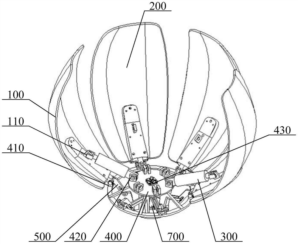
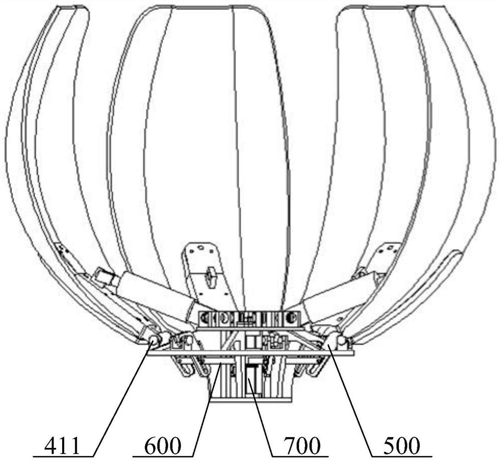
[0046] like figure 1 , figure 2 As shown, the mechanical petal decoration structure provided by this embodiment includes: active petal 100, driven petal 200, electric push rod 300, base 400, transmission part 500, moving plate 600 and guide rod 700; active petal 100 and driven The petals 200 are all rotatably connected with the base 400, and two electric push rods 300 are provided, and the two electric push rods 300 are symmetrically arranged on the base 400, and the two electric push rods 300 are respectively connected with two symmetrically arranged active petals 100. , to drive the two active petals 100 to rotate relative to the base 400; the guide rod 700 is arranged in the middle of the base 400, and the guide rod 700 is connected with the base 400, the guide rod 700 is provided with a sliding path, and the active petal 100 and the driven petal 200 are both A transmission part 500 is provided, and the plurality of transmission parts 500 are connected with the moving plate 600 . The moving plate 600 is slidably connected with the guide rod 700 , and the moving plate 600 moves along the sliding path to drive the plurality of transmission parts 500 to rotate synchronously.
[0047]Specifically, the petals in the mechanical petal decoration structure are divided into active petals 100 and driven petals 200. The active petals 100 and the driven petals 200 have the same structure. The driving end of the electric push rod 300 acts on the active petals 100. When the petals are used, the two electric push rods 300 are activated synchronously, and the generated force acts on the two active petals 100, so that the two active petals 100 rotate relative to the base 400, and the active petals 100 rotate at the same time. The transmission part 500 rotates, so that the transmission part 500 drives the moving plate 600 to move upward along the guide rod 700 , the moving plate 600 moves upward and drives other transmission parts 500 connected with the driven petals 200 to rotate, thereby connecting the driven petals 200 The transmission part 500 of the device drives the driven petals 200 to rotate, so as to realize the opening and closing of the active petals 100 and the driven petals 200 .
[0048] The mechanical petal decoration structure provided in this embodiment includes: an active petal 100, a driven petal 200, an electric push rod 300, a base 400, a transmission part 500, a moving plate 600 and a guide rod 700; the electric push rod 300 drives the active petal 100 Rotating around the base 400, when the active petal 100 rotates around the base 400, the transmission part 500 connected with the active petal 100 rotates, and drives the moving plate 600 to move along the sliding path provided by the guide rod 700, and the moving plate 600 moves and drives and drives at the same time. The transmission part 500 connected with the petals 200 rotates, and drives the driven petals 200 to rotate around the base 400, thereby realizing the synchronous opening and closing of the driven petals 200 and the active petals 100, effectively reducing the number of driving motors used, and alleviating the existing problems in the prior art. Mechanical petal drive motors are used in a large number, resulting in technical problems such as high cost and complex structure.
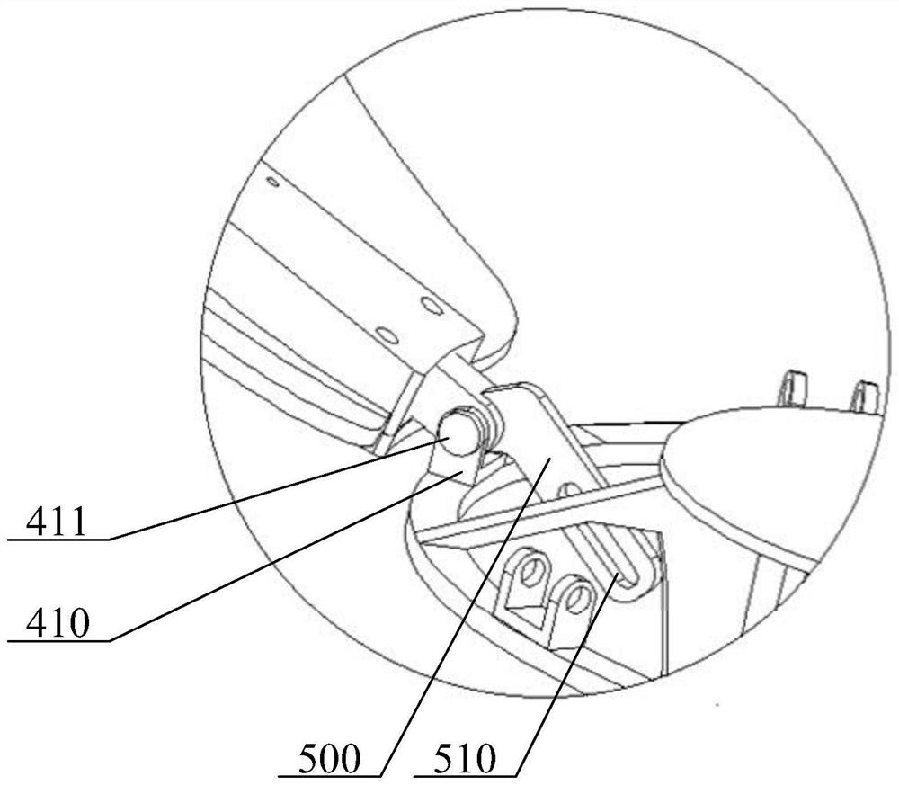
[0049] On the basis of the above-mentioned embodiment, as image 3 As shown, in an optional embodiment, in the mechanical petal device structure provided in this embodiment, a plurality of hinge bases 410 are evenly spaced along the circumferential direction of the base 400, and the hinge base 410 is provided with a rotating shaft 411, The active petals 100 and the driven petals 200 are respectively rotatably connected with the rotating shafts 411 on the plurality of hinge bases 410 ; the transmission part 500 is rotatably connected with the rotating shafts 411 .
[0050] Specifically, a plurality of hinge bases 410 are evenly spaced on the base 400, and each hinge base 410 is provided with a rotating shaft 411, and the rotating shaft 411 passes through the driving petal 100 or the driven petal 200 and the transmission part 500, so that the The transmission part 500 connected with the driving petal 100 rotates around the rotation axis 411 , and the transmission part 500 connected with the driven petal 200 rotates around the rotation axis 411 .
[0051] It should be noted that the number of rotating seats is the sum of 100 active petals and 200 driven petals.
[0052] In an optional embodiment, the transmission part 500 includes a transmission rod; the transmission rod is rotatably connected to the hinge base 410, and the end of the transmission rod is snapped with the driving petal 100 or the driven petal 200, so that the driving rod is connected to the driving petal 100 or 200 driven petals rotate synchronously.
[0053] Specifically, the end of the transmission rod can extend into the driving petal 100 or the driven petal 200, and the other end of the driving rod is connected with the moving plate 600 to ensure the synchronous rotation of the driving rod and the driving petal 100 or the driven petal 200.
[0054] like Image 6 As shown, in an optional embodiment, the moving plate 600 includes a flange member 610 and a lifting rod 620; the flange member 610 is slidably connected with the guide rod 700 through a sliding bearing, and one end of the lifting rod 620 is connected with the flange member 610, The other end of the lift rod 620 is connected with the transmission rod.
[0055] Specifically, the number of the lifting rods 620 is set in a one-to-one correspondence with the number of the transmission rods, the two ends of the lifting rods 620 are respectively connected with the transmission rod and the flange member 610 , and the flange member 610 passes the sliding bearing along the axis direction of the guide rod 700 . Move, when the flange member 610 moves down along the guide rod 700, the active petals 100 and the driven petals 200 are retracted, and when the flange member 610 moves up along the guide rod 700, the active petals 100 and the driven petals 200 Open.
[0056] In an optional embodiment, the transmission rod is provided with a sliding groove 510 , the end of the lifting rod 620 is provided with a rotating bearing, and the rotating bearing is located in the sliding groove 510 .
[0057] Specifically, the transmission rod is provided with a sliding groove 510, and the rotating bearing at the end of the lifting rod 620 is arranged in the sliding groove 510, so that the rotating bearing at the end of the lifting rod 620 slides in the sliding groove 510, thereby making the lifting rod 620 move up and down Drive the rotational movement of the transmission rod.
[0058] like Figure 4 As shown, in an optional embodiment, one end of the active petal 100 and the driven petal 200 close to the transmission rod is provided with a snap groove 120, the end of the drive rod has a snap protrusion 520, and the snap protrusion 520 extends into into the snap slot 120 .
[0059] Specifically, the ends of the driving petals 100 and the driven petals 200 both have a snap-fit groove 120, and the snap-fit protrusions 520 at the end of the transmission rod protrude into the snap-fit grooves 120, so that the driving petal 100 or the driven petal 200 is connected to the snap-fit groove 120. The transmission rod rotates synchronously.
[0060] like Figure 5 As shown, in an optional embodiment, the snap-on protrusion 520 has a right-angled side 530 , the groove wall of the snap-fit slot 120 forms the snap-on side, and the right-angled side 530 fits with the snap-on side.
[0061] Specifically, in order to realize the clamping connection between the clamping protrusion 520 and the clamping groove 120 , the clamping protrusion 520 has a right-angled side 530 to form a right angle, and the groove wall of the clamping groove 120 corresponds to the card matched with the right-angled side 530 . The right-angle side 530 and the clamping side are attached to each other, so that the clamping protrusion 520 and the transmission rod can rotate synchronously.
[0062] In an optional embodiment, the base 400 is provided with a first rotating base 420 , and one end of the electric push rod 300 is rotatably connected to the first rotating base 420 .
[0063] Specifically, a plurality of first rotating seats 420 are evenly spaced along the circumferential direction of the base 400 . Symmetrical settings.
[0064] In an optional embodiment, the active petal 100 is provided with a second rotating base 110 , and one end of the electric push rod 300 away from the first rotating base 420 is rotatably connected to the second rotating base 110 .
[0065] Specifically, each active petal 100 is provided with a second rotating base 110 , and the end of the electric push rod 300 is connected to the second rotating base 110 . The push rod 300 drives the active petal 100 to rotate around the hinge base 410 .
[0066] In an optional embodiment, the base 400 is provided with a fixing base 430 , and the base 400 is connected to the guide rod 700 through the fixing base 430 .
[0067] Specifically, a fixing seat 430 is provided on the base 400 , and the position of the guide rod 700 is fixed by the fixing seat 430 , so that the guide rod 700 is at the center of the base 400 , and the connection stability of the guide rod 700 is ensured.
[0068] In the mechanical petal decoration structure provided in this embodiment, by setting the right-angled edges 530 on the snap-on protrusions 520 and the snap-on edges in the snap-fit grooves 120, the synchronous rotation of the transmission rod and the driving petals 100 or the driven petals 200 is realized, The driving rod and the moving plate 600 are used to drive the active petals 100 and the driven petals 200 to open and close synchronously.
[0069] In addition, if the number of electric push rods 300 is the same as the number of petals, the transmission rod and flange 610 are not required, the petals are independently controlled by the electric push rod 300, and the movement of the electric push rod 300 can realize the opening and closing of the petals.
[0070] Finally, it should be noted that the above embodiments are only used to illustrate the technical solutions of the present invention, but not to limit them; although the present invention has been described in detail with reference to the foregoing embodiments, those of ordinary skill in the art should understand that: The technical solutions described in the foregoing embodiments can still be modified, or some or all of the technical features thereof can be equivalently replaced; and these modifications or replacements do not make the essence of the corresponding technical solutions deviate from the technical solutions of the embodiments of the present invention. scope.