Element test system and method

A component testing and component technology, applied in the direction of single semiconductor device testing, transmission system, electrical components, etc., can solve the problems of inconvenience, general products and methods without suitable structures and methods, etc., to reduce the number of uses, maintain test performance, Effect of equipment cost reduction

Inactive Publication Date: 2011-01-12
ACCTON TECHNOLOGY CORPORATION
View PDF0 Cites 7 Cited by
  • Summary
  • Abstract
  • Description
  • Claims
  • Application Information

AI Technical Summary

Problems solved by technology

[0009] It can be seen that the above-mentioned existing component testing system and method thereof obviously still have inconvenience and defects in product structure, manufacturing method and use, and need to be further improved urgently.
In order to solve the above-mentioned problems, the relevant manuf

Method used


Image

  • Element test system and method
  • Element test system and method
  • Element test system and method

Examples


Example Embodiment

[0041] In order to further explain the technical means and effects that the present invention adopts to achieve the intended purpose of the invention, below in conjunction with the accompanying drawings and preferred embodiments, the specific implementation, structure, method, Steps, features and effects thereof are described in detail below.

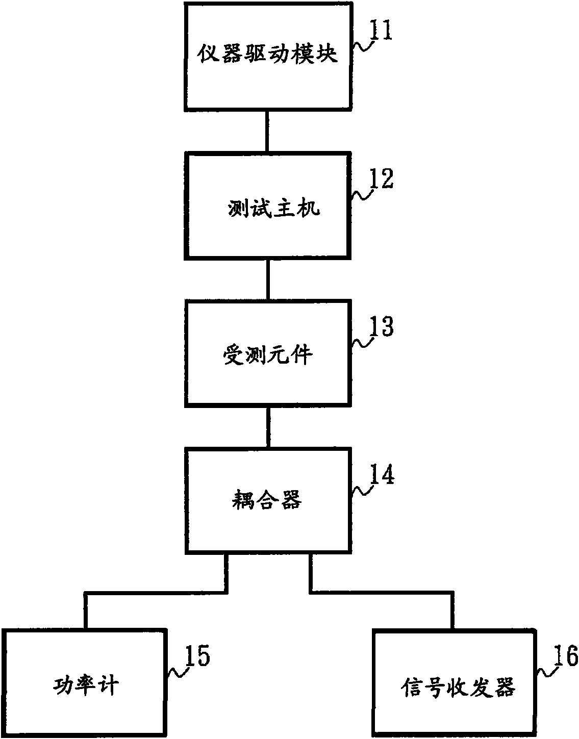
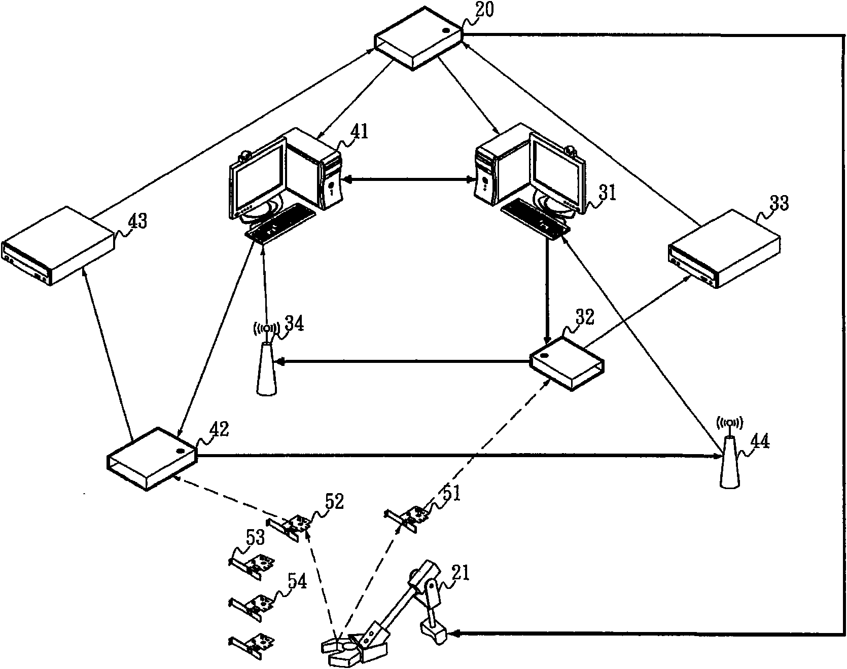
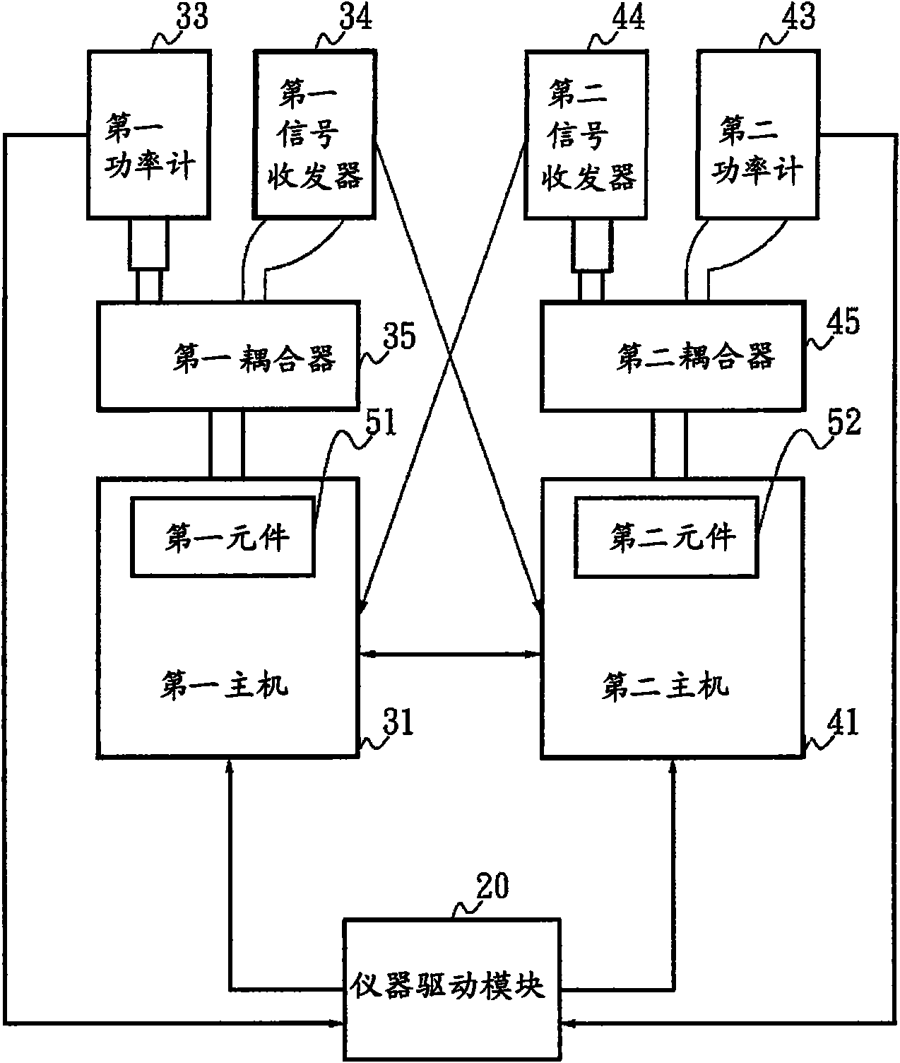
[0042] Please also refer to Figure 2A and Figure 2B as shown, Figure 2A It is a test system architecture diagram of an embodiment of the present invention, Figure 2B It is a block diagram of the test system of the embodiment of the present invention. The system disclosed in the present invention includes a first testing device, a second testing device, a loading and unloading module 21 and an instrument driving module 20 .

[0043] The first test equipment includes a first host 31, a first power meter 33 and a first signal transceiver 34; the second test equipment includes a second host 41, a second power meter 43 and a second s...


PUM


Abstract

The invention relates to an element test system and an element test method. In the element test system, first equipment tests a first element when monitoring the first element is loaded; second test equipment detects a second element when monitoring the second element is loaded; an apparatus driving module controls a loading and unloading module to load a first element on the first test equipmentand controls the loading and unloading module to load the second element on the second test equipment when the first test equipment test the first element; and the time for loading the elements onto or unloading the elements from the first test equipment and the second equipment are staggered by controlling the loading and unloading module, so that the first equipment and the second equipment test the first element and the second element parallelly.

Description

technical field [0001] The present invention relates to a component testing system and its method, in particular to a component testing system and its method which stagger the time of loading or unloading components on two testing devices so that the two testing devices can execute component testing operations in parallel. Background technique [0002] In the prior art, the manufacturer performs a test operation on each tested component after manufacturing the tested component. [0003] Please refer to figure 1 As shown, it is a block diagram of a component testing system in the prior art, which is composed of an instrument driver module 11 , a test host 12 , a power meter (Power Meter, PM) 15 and a signal transceiver 16 . Wherein, the test host 12 is connected to the instrument driver module 11 , and is connected to the power meter 15 and the signal transceiver 16 through the coupler 14 . The power meter 15 is used to detect the signal strength of the signal (such as Radi...

Claims


Application Information

Patent Timeline
IPC IPC(8): G01R31/00G01R31/26G01R31/28H04B17/00
Inventor 骆文彬刘钊平施云严
Owner ACCTON TECHNOLOGY CORPORATION
Why Eureka
Try Eureka