
Sparse array-based imaging method and imaging device

A sparse array, cross-direction technology, applied in the field of imaging methods and imaging devices based on sparse arrays, can solve the problems of high system complexity, large number of 3D-SAR array elements, and high cost, so as to reduce costs and facilitate data storage , the effect of reducing the amount of use

Active Publication Date: 2019-04-09
INNER MONGOLIA UNIV OF TECH
View PDF11 Cites 7 Cited by
  • Summary
  • Abstract
  • Description
  • Claims
  • Application Information

AI Technical Summary

Problems solved by technology

By using the imaging method and imaging device provided by the present invention, the problems of large number of array elements, high system complexity, and high cost of the 3D-SAR array existing in the prior art can be solved, thereby providing a low-cost and high-efficiency Imaging method and imaging device based on sparse array for imaging effect

Method used


Image

  • Sparse array-based imaging method and imaging device
  • Sparse array-based imaging method and imaging device
  • Sparse array-based imaging method and imaging device

Examples


Embodiment Construction

[0063] Below, specific embodiments of the present invention will be described in detail in conjunction with the accompanying drawings, but they are not intended to limit the present invention.

[0064] It should be understood that various modifications may be made to the embodiments disclosed herein. Accordingly, the above description should not be viewed as limiting, but only as exemplifications of embodiments. Those skilled in the art will envision other modifications within the scope and spirit of the disclosure.

[0065]The accompanying drawings, which are incorporated in and constitute a part of this specification, illustrate embodiments of the disclosure and, together with the general description of the disclosure given above and the detailed description of the embodiments given below, serve to explain the embodiments of the disclosure. principle.

[0066] These and other characteristics of the invention will become apparent from the following description of preferred ...


PUM


Abstract

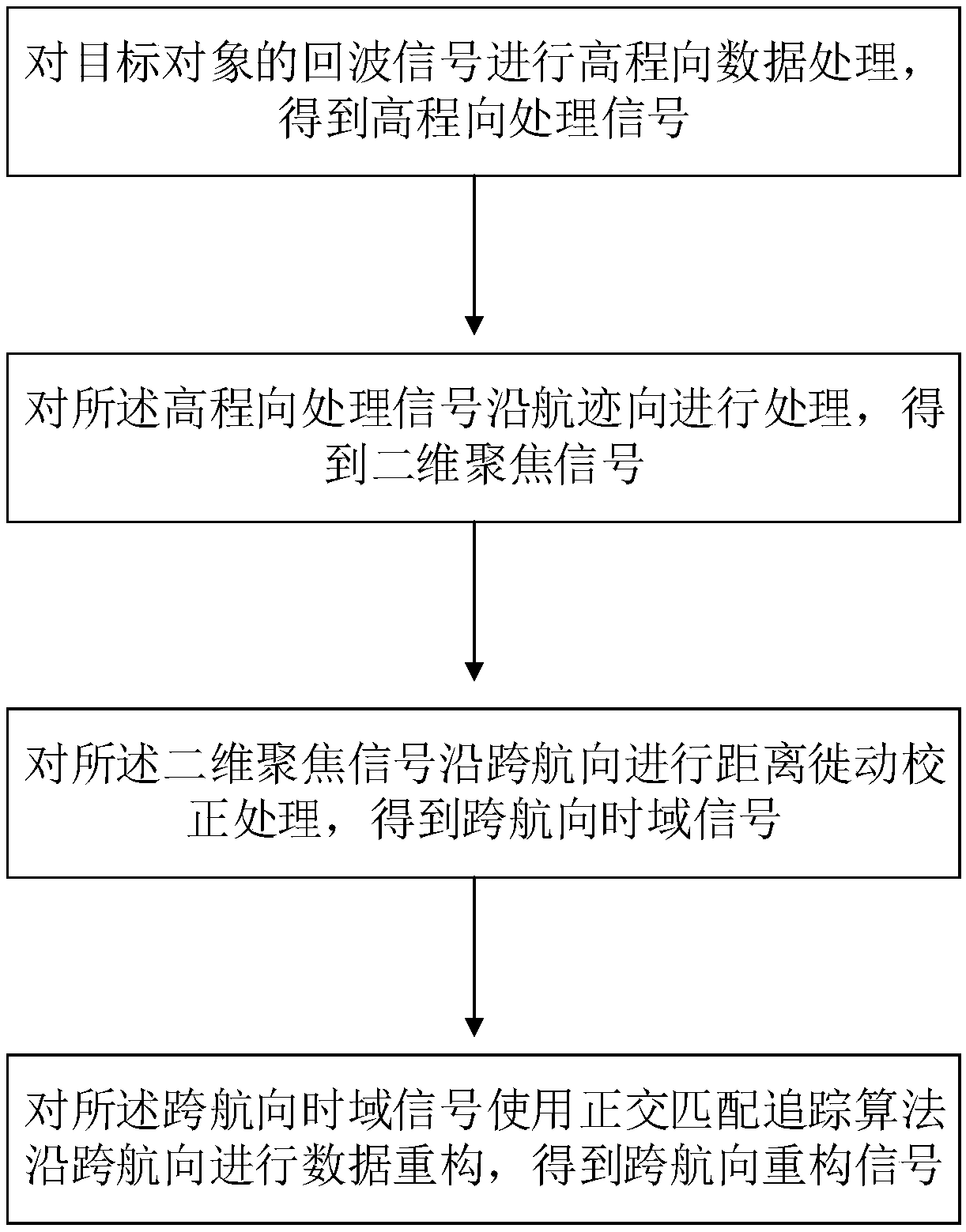
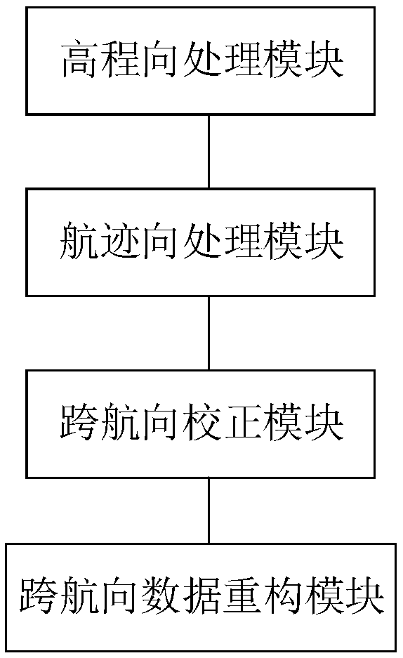
Embodiments of the invention provide a sparse array-based imaging method and imaging device. The method comprises steps of performing elevation data processing on an echo signal of a target object soas to obtain an elevation processing signal; processing the elevation processing signal in a track direction so as to obtain a two-dimensional focus signal; performing distance migration correction processing on the two-dimensional focus signal in a transverse direction so as to obtain a transverse time domain signal; performing data reconstruction on the transverse time domain signal by using anorthogonal matching pursuit algorithm in the transverse direction so as to obtain a transverse reconstruction signal, and generating, based on the sparse array and using the transverse reconstructionsignal, a three-dimensional SAR image of the target object. Through adoption of the imaging method and imaging device, problems of a large number of array elements in a 3D-SAR array, highly complex system and high cost in the prior art are solved.

Description

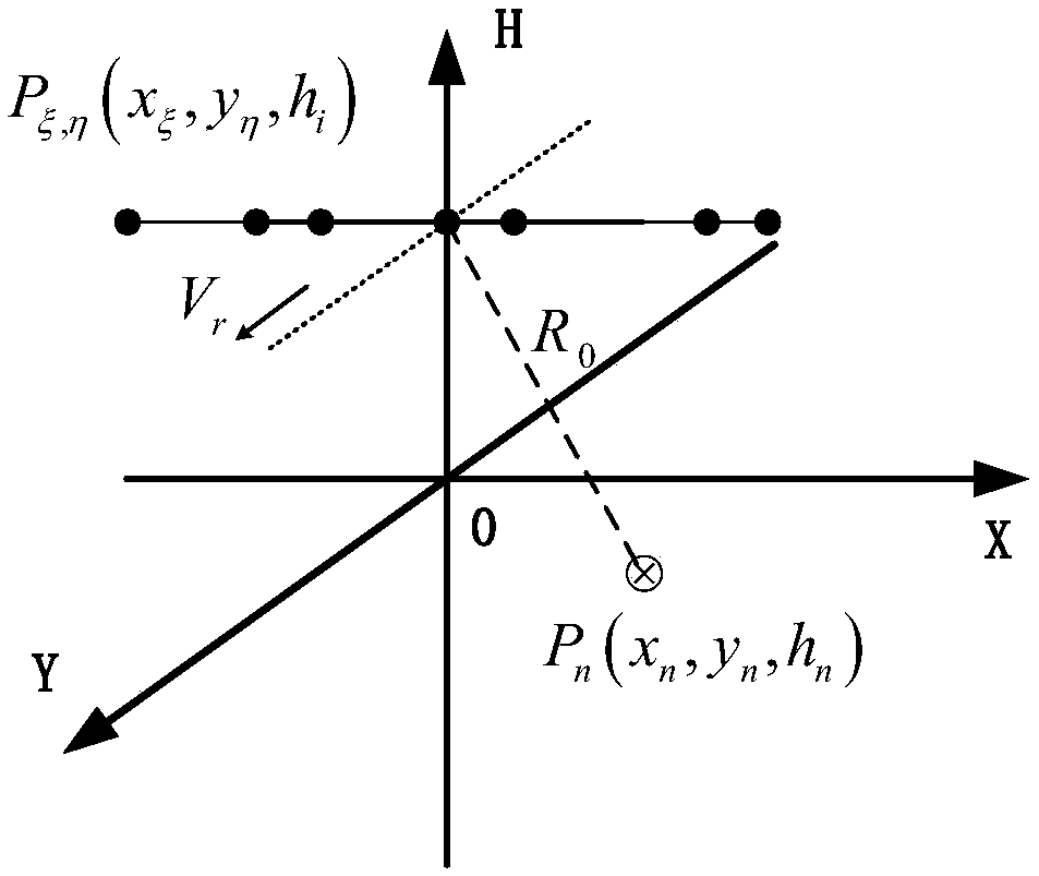
technical field [0001] The invention relates to the technical field of microwave imaging technology for earth observation, in particular to an imaging method and an imaging device based on a sparse array. Background technique [0002] Array down-looking 3D-SAR uses the transceiver array to obtain the equivalent phase center of the antenna, and can obtain 3D echo data and realize 3D imaging through one flight, thereby avoiding the de-correlation problem caused by multiple flights; The imaging geometry has the largest radar beam grazing angle, which can well solve the problems of shadows and overlapping in side-looking SAR imaging. This feature is especially beneficial for observations in areas with large terrain fluctuations. Array down-looking 3D-SAR has wide application potential in military reconnaissance and military target interpretation, complex terrain mapping, urban building extraction, disaster rescue and other fields. [0003] Although array down-looking 3D-SAR has...

Claims


Application Information

Patent Timeline
IPC IPC(8): G01S13/90G01S7/41
CPCG01S7/41
Inventor 徐伟李婷婷黄平平谭维贤李亚超张振华
Owner INNER MONGOLIA UNIV OF TECH
Learn More