Efficient machining equipment and machining process for high-strength flange

A kind of processing equipment and high-strength technology, applied in the direction of metal processing equipment, milling machine equipment, milling machine equipment details, etc., can solve the problem of low flange processing efficiency, achieve the effect of difficult positioning process, difficult processing accuracy, and improve processing efficiency

Pending Publication Date: 2022-07-22
嘉兴市智刃机械设备有限公司
View PDF0 Cites 1 Cited by
  • Summary
  • Abstract
  • Description
  • Claims
  • Application Information

AI Technical Summary

Problems solved by technology

[0003] However, when the processed blank is removed and the unprocessed blank is installed, the equipment needs to be shut down, and the processing can only be continued after the new blank is removed and installed, and the processing of the blank is stopped during the shutdown of the equipment , resulting in lower efficiency of flange processing

Method used


Image

  • Efficient machining equipment and machining process for high-strength flange
  • Efficient machining equipment and machining process for high-strength flange
  • Efficient machining equipment and machining process for high-strength flange

Examples


Embodiment Construction

[0039] The present application will be further described in detail below with reference to the accompanying drawings.

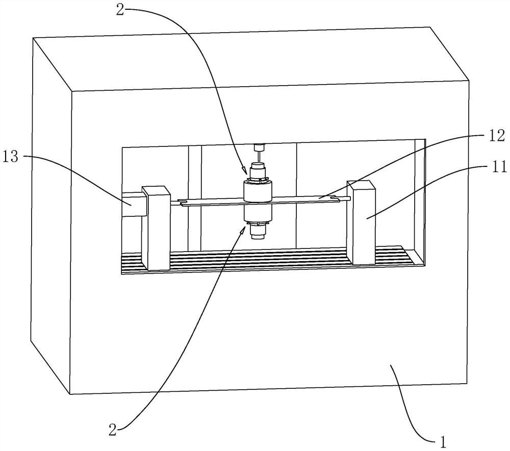
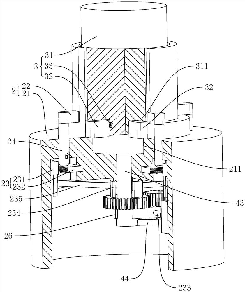
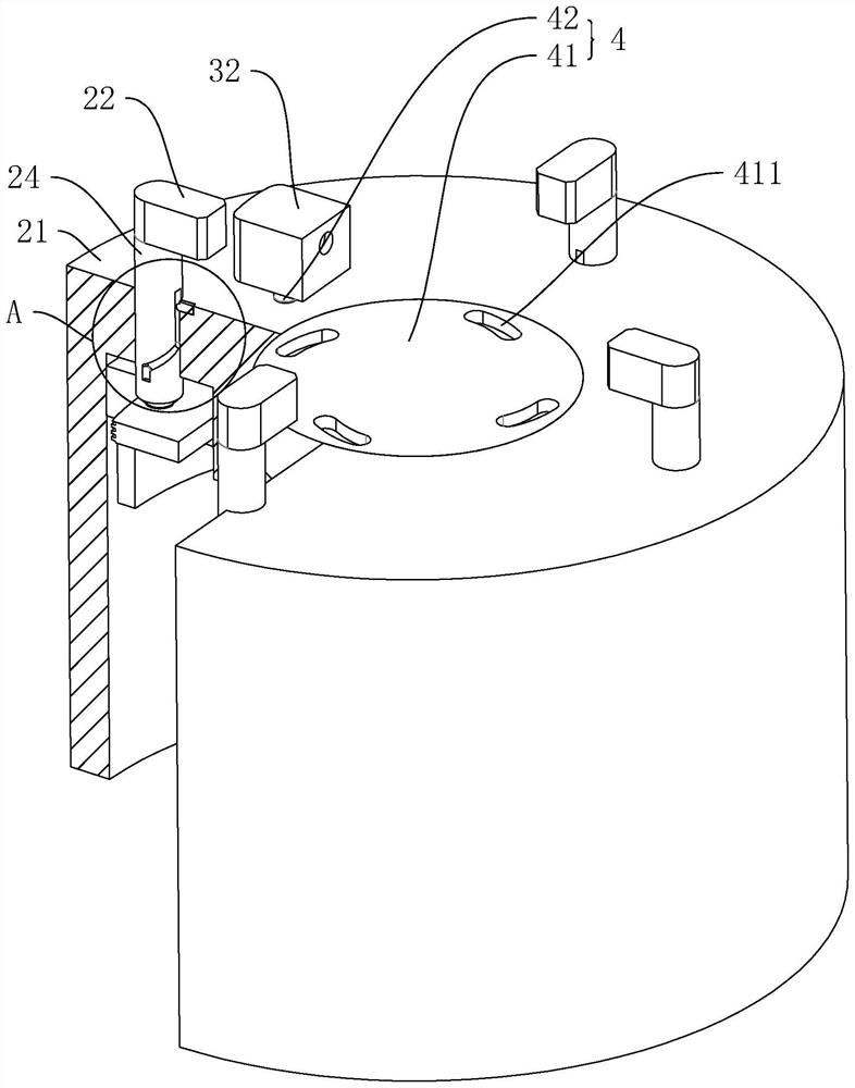
[0040] The high-efficiency processing equipment for high-strength flanges disclosed in this application, such as figure 1 As shown, it includes a milling machine 1, a fixed base 11 arranged on the machine table, a rotating base 12 that rotates horizontally on the fixed base 11, a rotating member 13 that drives the rotating base 12 to rotate, and a rotating member 13 disposed on the rotating base 12 for clamping Workpiece clamping mechanism 2. There are two fixed seats 11 , both of which are fixed on the upper end surface of the milling machine 1 table with bolts, and there is a gap between them. The rotating member 13 is a servo motor, and the rotating member 13 is fixed to the side wall of a fixed base 11 away from the rotating base 12 by bolts. The member 13 drives the rotary base 12 to reciprocate along the horizontal axis. like figure 2 and image 3...


PUM


Abstract

The efficient machining equipment comprises a milling machine, a fixed seat, a rotating seat, a rotating piece and clamping mechanisms, the clamping mechanisms are arranged on the two sides of the rotating axis of the rotating seat, the rotating piece is arranged on the fixed seat, and the driving end of the rotating piece is connected with the rotating seat; the clamping mechanism comprises a clamping seat, a plurality of clamping blocks arranged on the clamping seat and a clamping driving part for driving the clamping blocks to move, the clamping blocks move perpendicular to the rotating axis of the rotating seat, and the end faces, close to the clamping seat, of the clamping blocks can abut against the end faces, away from the clamping seat, of the workpieces. Clamping mechanisms used for clamping workpieces can be arranged on the two side walls, away from each other, of the rotating base, at the moment, when the milling machine machines the workpieces clamped on one clamping mechanism, the other clamping mechanism can be used for taking and feeding the workpieces, and at the moment, the situation that the milling machine stops during taking and discharging is avoided; therefore, the overall efficiency of flange machining is improved.

Description

technical field [0001] The present application relates to the technical field of flange processing, in particular to a high-efficiency processing equipment and processing technology for high-strength flanges. Background technique [0002] At present, during the processing of the flange used on the planetary reducer, the blank of the flange is usually placed on the jig of the processing equipment, and the blank is fastened with the jig before processing. The blank is removed from the jig and the unprocessed blank is placed on the jig. [0003] However, when the processed blank is removed and the unprocessed blank is installed, the equipment needs to be shut down, and the processing can be continued after the new blank is removed and installed, and the processing of the blank is stopped during the equipment shutdown. , resulting in lower efficiency of flange processing. [0004] Therefore, it is necessary to propose a new technical solution to solve the above problems. SUM...

Claims


Application Information

Patent Timeline
Patent Type & Authority Applications(China)
IPC IPC(8): B23C3/00B23C9/00B23Q1/26B23Q3/06
CPCB23C3/00B23C9/00B23Q3/06B23Q1/26
Inventor 单皓琦
Owner 嘉兴市智刃机械设备有限公司
Why Eureka
Try Eureka