Medical waste storage box

A technology for medical waste and storage boxes, applied in the directions of household appliances, garbage collection, trash cans, etc., can solve the problem of inconvenient adjustment of the position and height of the crossbar, troublesome movement of the medical waste storage box, easy downward sliding of the medical waste storage box, etc. question

Pending Publication Date: 2022-07-22
颍上县人民医院
View PDF0 Cites 0 Cited by
  • Summary
  • Abstract
  • Description
  • Claims
  • Application Information

AI Technical Summary

Problems solved by technology

[0003] Most of the common medical waste storage boxes on the market are not easy to adjust the position and height of the crossbar, which makes it more troublesome for staff of different heights to push the medical waste storage box to move, and the medical waste storage box is easy to slide down when passing through the slope for rest. , for this purpose, we propose a medical waste storage bin

Method used


Image

  • Medical waste storage box
  • Medical waste storage box
  • Medical waste storage box

Examples


Embodiment 1

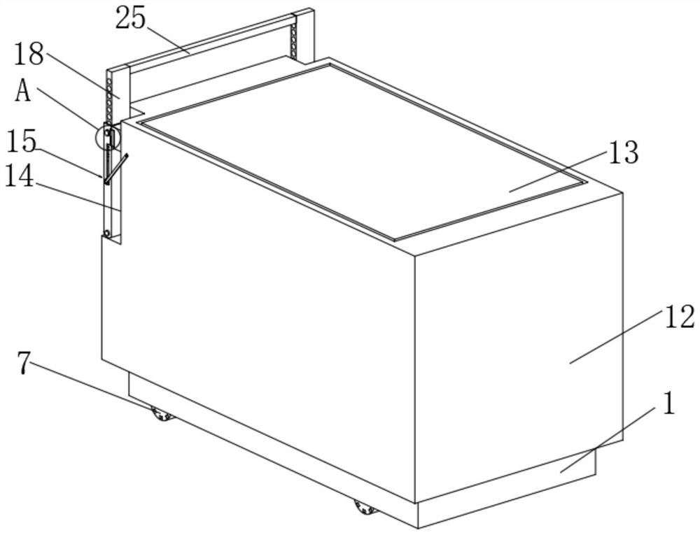
[0026] see Figure 1-6 , the present invention provides a technical solution: a medical waste storage box, comprising a base 1, the bottom end of the base 1 is provided with grooves 2 near the corners, the groove 2 is provided with a braking mechanism 3, and the upper end of the base 1 is provided with There is a box body 12, the upper end of the box body 12 is provided with a box cover 13, one side of the box body 12 near the corners is provided with a receiving slot 14, the inner side wall of the receiving slot 14 is provided with a flap 26 near the top, and one side of the flap 26 is provided A second magnetic sheet 27 is provided, and a pull rod mechanism 15 is provided inside the receiving slot 14 .

[0027] see Figure 5 The pull rod mechanism 15 includes a pull rod 16, the upper end of the pull rod one 16 is provided with a vertical chute 17, a pull rod two 18 is provided between the inner side walls of the vertical chute 17, and the side wall of the pull rod two 18 is...

Embodiment 2

[0032] see Figure 1-4 , the present invention provides a technical solution: a medical waste storage box, comprising a base 1, the bottom end of the base 1 is provided with grooves 2 near the corners, the groove 2 is provided with a braking mechanism 3, and the upper end of the base 1 is provided with There is a box body 12, the upper end of the box body 12 is provided with a box cover 13, one side of the box body 12 near the corners is provided with a receiving slot 14, the inner side wall of the receiving slot 14 is provided with a flap 26 near the top, and one side of the flap 26 is provided A second magnetic sheet 27 is provided, and a pull rod mechanism 15 is provided inside the receiving slot 14 .

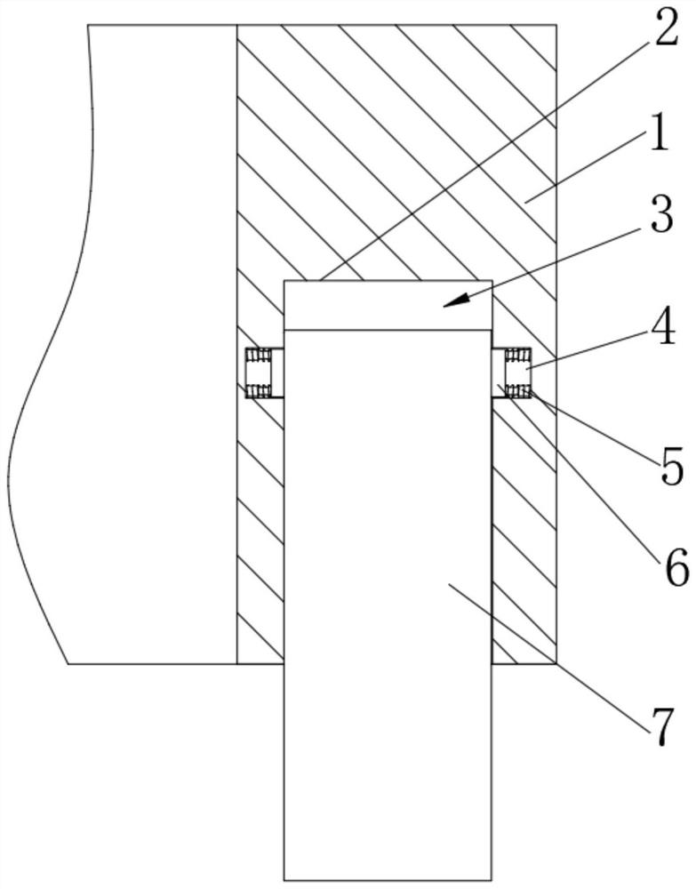
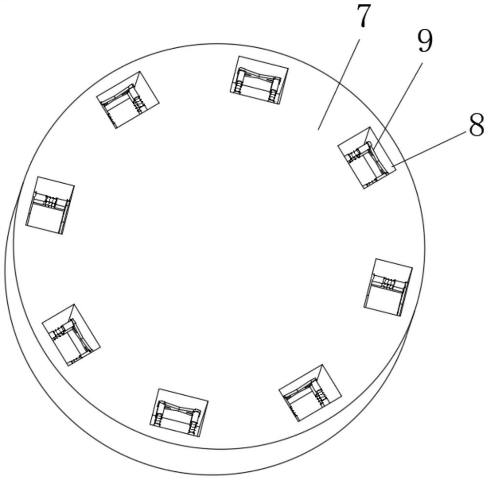
[0033] see Figure 2-4 , the braking mechanism 3 includes a movable groove 4, the inner side wall of the movable groove 4 is provided with a telescopic rod 5 near the corners, one end of the telescopic rod 5 is provided with a limit plate 6, and the groove 2 is provided wit...


PUM


Abstract

The medical waste storage box comprises a base, grooves are formed in the positions, close to the corners, of the bottom end of the base, braking mechanisms are arranged in the grooves, a box body is arranged at the upper end of the base, a box cover is arranged at the upper end of the box body, and storage grooves are formed in the positions, close to the corners, of one side of the box body. A lapping plate is arranged at the position, close to the top, of the inner side wall of the storage groove, a second magnetic sheet is arranged on one side of the lapping plate, a pull rod mechanism is arranged in the storage groove, the brake mechanism comprises a movable groove, telescopic rods are arranged at the positions, close to the corners, of the inner side wall of the movable groove, and a limiting plate is arranged at one end of each telescopic rod. According to the medical waste storage box, workers can conveniently adjust the height of the transverse rod according to themselves, the medical waste storage box can be conveniently used by the workers with different heights, downward pushing force applied to the base along the slope under the action of gravity of the box body is effectively reduced, the storage box is conveniently supported, and labor is saved.

Description

technical field [0001] The invention relates to the field of medical waste storage boxes, in particular to a medical waste storage box. Background technique [0002] Hospital waste refers to all wastes that need to be discarded and cannot be reused in hospitals, including biological and non-biological wastes, as well as domestic wastes. It contains a large number of pathogenic microorganisms and harmful chemical substances, and even radioactive and damaging substances. Therefore, medical waste is an important risk factor for disease transmission or related public health problems. This storage box can store medical waste for the convenience of staff. deal with; [0003] Common medical waste storage boxes on the market, the position and height of most of the bars are inconvenient to adjust, which makes it difficult for staff of different heights to move the medical waste storage box, and the medical waste storage box is easy to slide down when passing through the slope to res...

Claims


Application Information

Patent Timeline
IPC IPC(8): B65F1/00B65F1/14B65F1/16
CPCB65F1/00B65F1/1473B65F1/16
Inventor 汪路路
Owner 颍上县人民医院
Why Eureka
Try Eureka