Road surface unevenness measuring device

A road surface and measuring device technology, applied in the directions of roads, roads, road repair, etc., can solve the problems of small detection area and unscientific and rigorous road surface smoothness, and achieve the effect of large measurement area and convenient use.

Active Publication Date: 2022-07-22
烟台嘉祥矿业机械有限公司
View PDF12 Cites 0 Cited by
  • Summary
  • Abstract
  • Description
  • Claims
  • Application Information

AI Technical Summary

Problems solved by technology

[0004]The detection area of ​​the above scheme is small, and it is not scientific an...

Method used


Image

  • Road surface unevenness measuring device
  • Road surface unevenness measuring device
  • Road surface unevenness measuring device

Examples


specific Embodiment 1

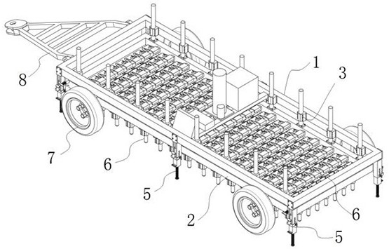
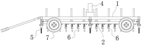
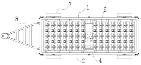
[0038] see Figure 1-4 As shown, the present invention is a road surface roughness measuring device, comprising an outer frame 1 and an inner frame 2; the inner frame 2 is linearly guided and matched with the outer frame 1 through a plurality of first linear ball guide bushes 3; There is a telescopic drive device 4 for driving the inner frame 2; a number of support adjustment devices 5 are installed on the periphery of the outer frame 1; a number of telescopic displacement measuring devices 6 are installed on the inner frame 2; four wheels 7 are installed on the outer frame 1; One end of the frame 1 is connected to the tractor through a trailer connecting frame 8 ; a power supply 9 and a signal collection display 10 are also installed on the outer frame 1 , and the signal collection display 10 is provided with a memory.

[0039] like Figure 5 As shown, the outer frame 1 includes a rectangular outer frame 101; the lower surfaces of the two frames in the length direction of th...

specific Embodiment 2

[0043] On the basis of the specific embodiment 1, the differences of this embodiment are:

[0044] like Figure 8-10 As shown, the support adjustment device 5 includes a guide groove body 51 connected with the outer frame 1, a jack 52 matched with the guide groove body 51, and a support slider 53; the guide groove body 51 includes an L-shaped plate 511; the L-shaped plate 511 It is connected with the outer frame 1 by bolts; the lower surface of the L-shaped plate 511 fixes the rectangular tube 512; the rectangular tube 512 is provided with a rectangular through slot 513 in the middle part; hole 514; the support slider 53 includes a rectangular column 531 slidably matched with the inner wall of the rectangular tube 512; a threaded through hole is opened at the axis of the rectangular column 531, and a threaded support column 532 is threaded on the threaded through hole; the upper end of the rectangular column 531 is An E-shaped support plate 533 is fixed on the same side of th...

specific Embodiment 3

[0046] On the basis of the second specific embodiment, the differences of this embodiment are:

[0047] like Figure 11 As shown, the telescopic displacement measuring device 6 includes a magnetostrictive displacement sensor 61, a second linear ball guide bush 62, a cylinder 63, a spring 64, and a mounting seat 65; the magnetostrictive displacement sensor 61 is threadedly mounted on the mounting seat 65; The mounting seat 65 is installed on the rectangular cross bar 23; the cylindrical cylinder 63 is linearly guided and matched with the second linear ball guide sleeve 62, and the upper end of the cylindrical cylinder 63 is provided with a limit ring plate 631; the second linear ball guide sleeve 62 is fixed and installed on the On the mounting seat 65; the magnetostrictive displacement sensor 61 coincides with the axis of the second linear ball guide 62, the cylinder 63 and the spring 64; the spring 64 is arranged between the limit ring plate 631 and the opposite surface of th...


PUM


Abstract

The invention discloses a road surface unevenness measuring device, and relates to the technical field of road measuring equipment. The device comprises an outer frame and an inner frame, the inner frame is in linear guide fit with the outer frame through a plurality of first linear ball guide sleeves; a telescopic driving device for driving the inner frame is mounted on the outer frame; a plurality of support adjusting devices are mounted on the peripheral side of the outer frame; a plurality of telescopic displacement measuring devices are mounted on the inner frame; four wheels are mounted on the outer frame; one end of the outer frame is connected with a tractor through a trailer connecting frame; and a power supply and a signal acquisition display are also mounted on the outer frame. Through the combination of the outer frame, the inner frame, the first linear ball guide sleeve, the telescopic driving device, the support adjusting device, the telescopic displacement measuring device, the wheels and the trailer connecting frame, the whole body is convenient to move and support at a fixed point, and the detection area is large; and calculating the range, variance and standard deviation of the displacement according to the displacement data list of the same group to reflect and evaluate the flatness of the road surface.

Description

technical field [0001] The invention belongs to the technical field of road measurement equipment, in particular to a road surface roughness measurement device. Background technique [0002] Roads are the infrastructure for all kinds of trackless vehicles and pedestrians; according to their use characteristics, they are divided into highways, urban roads, rural roads, factory and mine roads, forestry roads, test roads, competition roads, automobile test roads, and workshop passages. As well as school roads, among which high-demand roads are represented by airport runways. During the construction of the airport road, in order to ensure the quality of the road, it is necessary to measure the smoothness of the road. At present, the measurement of the road smoothness is generally measured by a spirit level. Whether the local road is smooth or not, causing local road bulges and depressions, affecting the quality of the road. [0003] The Chinese utility model patent with public...

Claims


Application Information

Patent Timeline
IPC IPC(8): E01C23/01
CPCE01C23/01
Inventor 杨军健于振海张艳
Owner 烟台嘉祥矿业机械有限公司
Why Eureka
Try Eureka