Pressure relief type waterproof technology
A pressure relief and technical technology, applied in the direction of roof drainage, roof insulation materials, roof covering, etc., can solve the problems of difficult construction, waterproof technology and long waterproof life, and achieve the effect of long waterproof period
- Summary
- Abstract
- Description
- Claims
- Application Information
AI Technical Summary
Problems solved by technology
Method used
Image

Examples
Embodiment 1
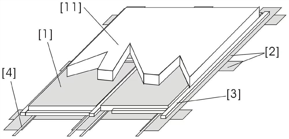
[0048] Example 1: as figure 1 As shown, the embodiment of the present invention provides a pressure relief waterproof technology, figure 1 The water-proof board [1] with good self-water resistance is processed into a non-wetting surface or provided with a continuous non-wetting surface, and the width of the non-wetting surface is larger than that of the surface as a non-wetting gasket. [2] The width of the contact with the waterproof board [1] is appropriate to prevent the leakage water from infiltrating or flowing to the center of the back surface of the waterproof board [1], and more surfaces of the waterproof board can be processed into non-wetting surfaces; A non-wetted gasket [2] of suitable width is laid flat on a flat surface or support, and the flashing plate [1] is installed on the non-wetting gasket [2] and the edge of the flashing plate [1] is placed on the non-wetting pad. The middle position of the sheet [2], so that the non-wetting surface between the waterproof...
Embodiment 2
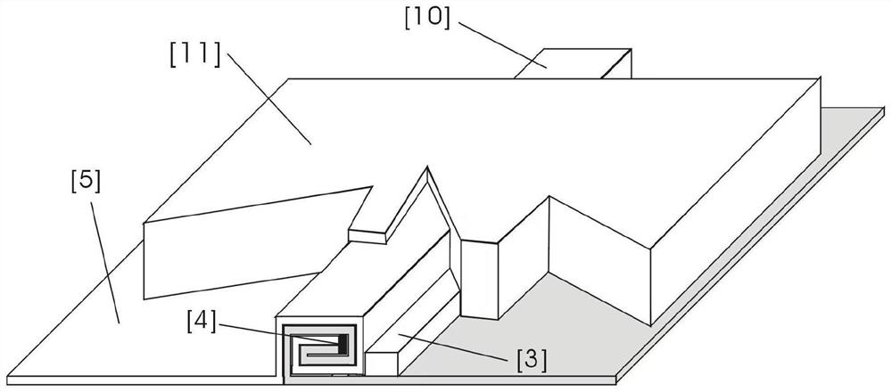
[0050] Example 2: Combination Figure 8 ,Will figure 1 The surrounding sides of the waterproof board [1] with good self-water resistance are processed into non-wetting surfaces or provided with continuous non-wetting surfaces, and the non-wetting parts [9] (or other suitable non-wetting parts) of suitable width and thickness The waterproof fittings) are tightly installed between the non-wettable surfaces around the sides of each waterproof board [1], and are installed or placed on the upper surface of the interface of the non-wettable surface where the waterproof board [1] and the non-wettable parts [9] are in close contact with each other. Put the hydrophilic drainage strip [3] and extend it into the drainage system as a pressure relief channel, and then seal the interface between each waterproof board [1] and the hydrophilic drainage strip [3] or seal the interface between the waterproof board [1] and the hydrophilic drainage strip [ 3] is covered with a suitable sealing ma...
Embodiment 3
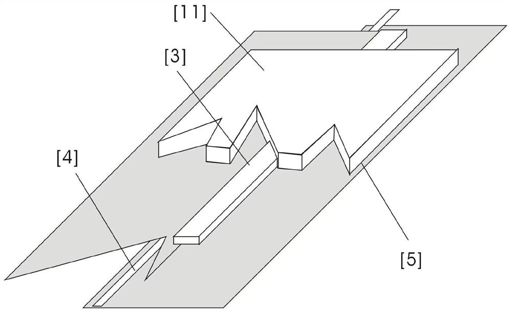
[0054] Example 3: Combination figure 2 , which is based on the foregoing embodiment, and the entire length of the waterproof material [5] that is similar to the width or length of the surface to be waterproofed or slightly longer is laid on the waterproof surface, and the waterproof material [5] is soft and easy to use. Deformed materials are suitable; the two waterproof materials [5] are overlapped with each other and tightly attached to each other, and the overlapping parts of the waterproof materials [5] are processed into a non-wetting surface, or the waterproof material [5] is more surface Processed into a non-wetting surface, install or place a hydrophilic drainage strip [3] on the water inlet side of the non-wetting surface interface where the two waterproof materials [5] are in close contact, and extend into the drainage system as a pressure relief channel. The interface of the material [5] is properly fixed or sealed or the upper surface of the waterproof material [5...
PUM
 Abstract
Description
Claims
Application Information
 - R&D
- Intellectual Property
- Life Sciences
- Materials
- Tech Scout
- Unparalleled Data Quality
- Higher Quality Content
- 60% Fewer Hallucinations
Browse by: Latest US Patents, China's latest patents, Technical Efficacy Thesaurus, Application Domain, Technology Topic, Popular Technical Reports.
© 2025 PatSnap. All rights reserved.Legal|Privacy policy|Modern Slavery Act Transparency Statement|Sitemap|About US| Contact US: help@patsnap.com