
Device and method for automatically detecting vehicle movement

A vehicle moving and automatic technology, applied in the field of garages, can solve problems such as car damage, and achieve the effect of finding parking spaces easily

Pending Publication Date: 2022-07-22
上海畅停信息科技有限公司
View PDF8 Cites 0 Cited by
  • Summary
  • Abstract
  • Description
  • Claims
  • Application Information

AI Technical Summary

Problems solved by technology

[0004] The purpose of the present invention is to solve the unmanned toll garage in the prior art. After the user parks the car, the garage lock will be activated, and the user needs to pay to unlock it. However, when some users forget to pay or want to escape the order, and there is no If you notice that there is a parking lock, you will not pay, and you will start the car. At this time, the car is prone to damage, and a device and method for automatically detecting vehicle movement are proposed.

Method used


Image

  • Device and method for automatically detecting vehicle movement
  • Device and method for automatically detecting vehicle movement
  • Device and method for automatically detecting vehicle movement

Examples


Embodiment 1

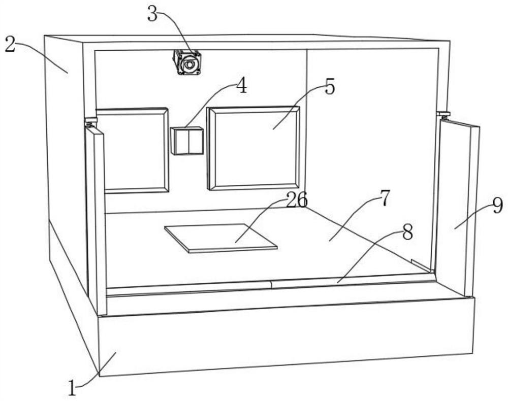
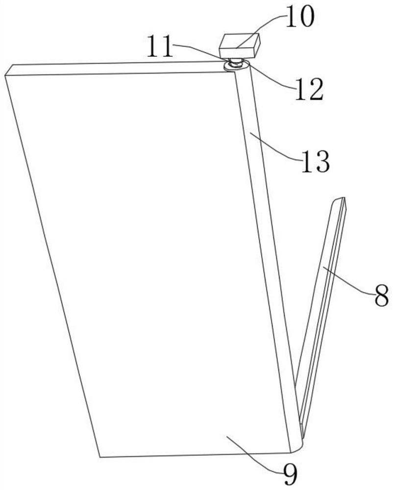
[0041] refer to Figure 1-10 , an automatic detection vehicle moving device, comprising a pre-embedded box 1, a garage 2 is fixedly connected to the top of the pre-embedded box 1, a laser detector 3 is fixedly connected to the inner wall of one side of the garage 2, and one side of the garage 2 is provided with two set of buffer components for buffering;

[0042] The inner wall of the pre-embedded box 1 is slidably connected with a bottom plate 7. Two symmetrically arranged second springs 23 are fixedly connected between the bottom of the bottom plate 7 and the bottom inner wall of the pre-embedded box 1. The bottom plate 7 is provided with a rectangular hole 22. The inside of the hole 22 slides through a lift box 26, and the inside of the lift box 26 is provided with a brake assembly for braking the vehicle;

[0043] The top of the embedded box 1 is provided with two sets of reminder components for prompting customers to pay.

Embodiment 2

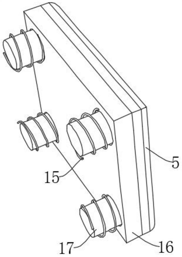
[0045] refer to Figure 1-10 , an automatic detection vehicle moving device, comprising a pre-embedded box 1, a garage 2 is fixedly connected to the top of the pre-embedded box 1, a laser detector 3 is fixedly connected to the inner wall of one side of the garage 2, and one side of the garage 2 is provided with two A set of buffer components for buffering, the buffer components include four sliding bars 17 that are fixedly connected to the inner wall of the garage 2 symmetrically in two pairs, and one side of the four sliding bars 17 is slidably connected with the same sliding plate 16, the sliding plate 16 A plurality of first springs 15 are fixedly connected between one side of the garage 2 and one side of the inner wall of the garage 2, the first springs 15 are sleeved on the sliding rod 17, and one side of the sliding plate 16 is fixedly connected with a rubber pad 5 for realizing buffer function;

[0046] The inner wall of the pre-embedded box 1 is slidably connected wit...


PUM


Abstract

The invention belongs to the field of garages, particularly relates to a device and a method for automatically detecting vehicle movement, and aims to solve the problems that according to an existing unmanned charging garage, after a user parks a vehicle, a garage lock can be started and can only be unlocked after the user pays, but some users forget to pay or want to escape an order and do not notice the parking space lock. According to the technical scheme, the garage comprises an embedded box, the top of the embedded box is fixedly connected with a garage body, the inner wall of one side of the garage body is fixedly connected with a laser detector, and one side of the garage body is provided with two buffering assemblies used for buffering. By arranging the braking assembly, braking of the vehicle can be achieved, the buffering assembly can prevent the vehicle from being damaged, the situation that a user forgets to pay can be greatly reduced by arranging the reminding assembly, and meanwhile when the user drives away the vehicle forcibly, all braking devices are removed at the same time, and the vehicle is prevented from being damaged.

Description

technical field [0001] The invention relates to the technical field of garages, and in particular, to a device and method for automatically detecting vehicle movement. Background technique [0002] A traditional garage is a brick and concrete garage, similar to a house! Also known as mechanical three-dimensional garage: the entire parking facility that uses machinery to access and park vehicles is called a mechanical parking garage, and a mechanical parking garage that is stored three-dimensionally is called a mechanical three-dimensional parking garage. The single-storey plane parking garage is the core, and the parking space can be changed in space through the unified management, monitoring 1 and PLC control of the garage through the host computer through the microcomputer, so that the parking space can be transformed from space to plane, so as to realize multi-level plane parking. function. [0003] The existing unmanned toll garage will activate the garage lock after t...

Claims


Application Information

Patent Timeline
Patent Type & Authority Applications(China)
IPC IPC(8): E04H6/42G08G1/017G07B15/02E06B3/36E05F1/12E05F15/619E05F17/00
CPCE04H6/42E04H6/422G08G1/0175G07B15/02E06B3/362E05F1/1223E05F15/619E05F17/004E05Y2900/132E05Y2900/106E05F2017/008
Inventor 聂光义李振军
Owner 上海畅停信息科技有限公司
Learn More