Electrical sealing device for protecting electrical element

A technology for sealing devices and electrical components, which is applied in the directions of sealing shells, transportation and packaging, and installation of support structures, etc. It can solve problems such as more adhesion, influence of heat dissipation effect, and blockage of dust-proof nets, so as to improve the effect of dust removal Effect

Inactive Publication Date: 2022-07-22
JIANGSU PROVINCE XUZHOU TECHNICIAN INST
View PDF0 Cites 0 Cited by
  • Summary
  • Abstract
  • Description
  • Claims
  • Application Information

AI Technical Summary

Problems solved by technology

Electronic components may be individual packages (resistors, capacitors, inductors, transistors, diodes, etc.), or groups of varying complexity, such as integrated circuits (op amps, resistors, logic gates, etc.), for To maintain the stability of the operation of electronic components, they are usually encapsulated with synthetic resin to improve insulation and protection from environmental influences. When the electrical components are used outdoors, a sealing device is used to seal and protect the electrical components, and the electrical components A lot of heat will be generated during use and operation. Generally, in order to facilitate heat dissipation, cooling holes will be opened on the outer wall of the sealed box for heat dissipation. Dust is intercepted, and after long-term use of the dust-proof net, more dust and debris will adhere to its surface. At this time, the mesh holes of the dust-proof net may be blocked, which will affect the heat dissipation effect in the later stage.

Method used


Image

  • Electrical sealing device for protecting electrical element
  • Electrical sealing device for protecting electrical element
  • Electrical sealing device for protecting electrical element

Examples


Embodiment

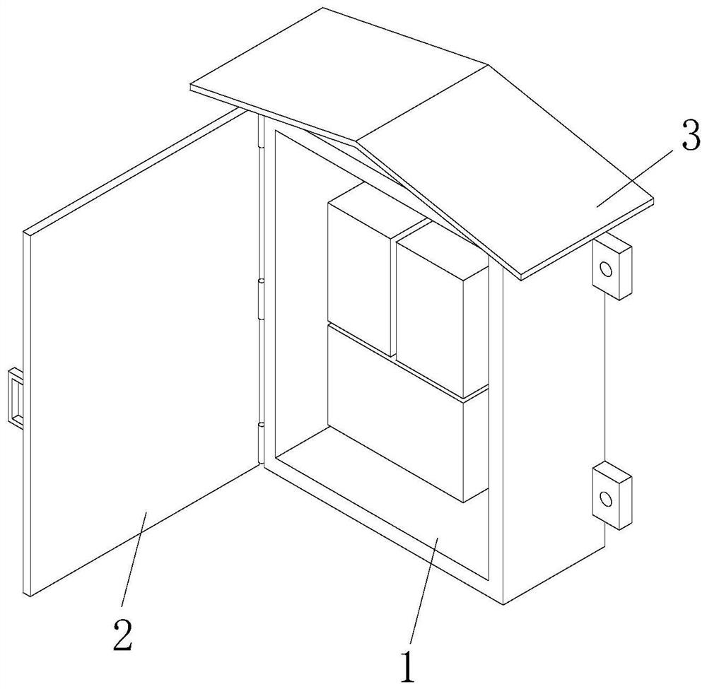
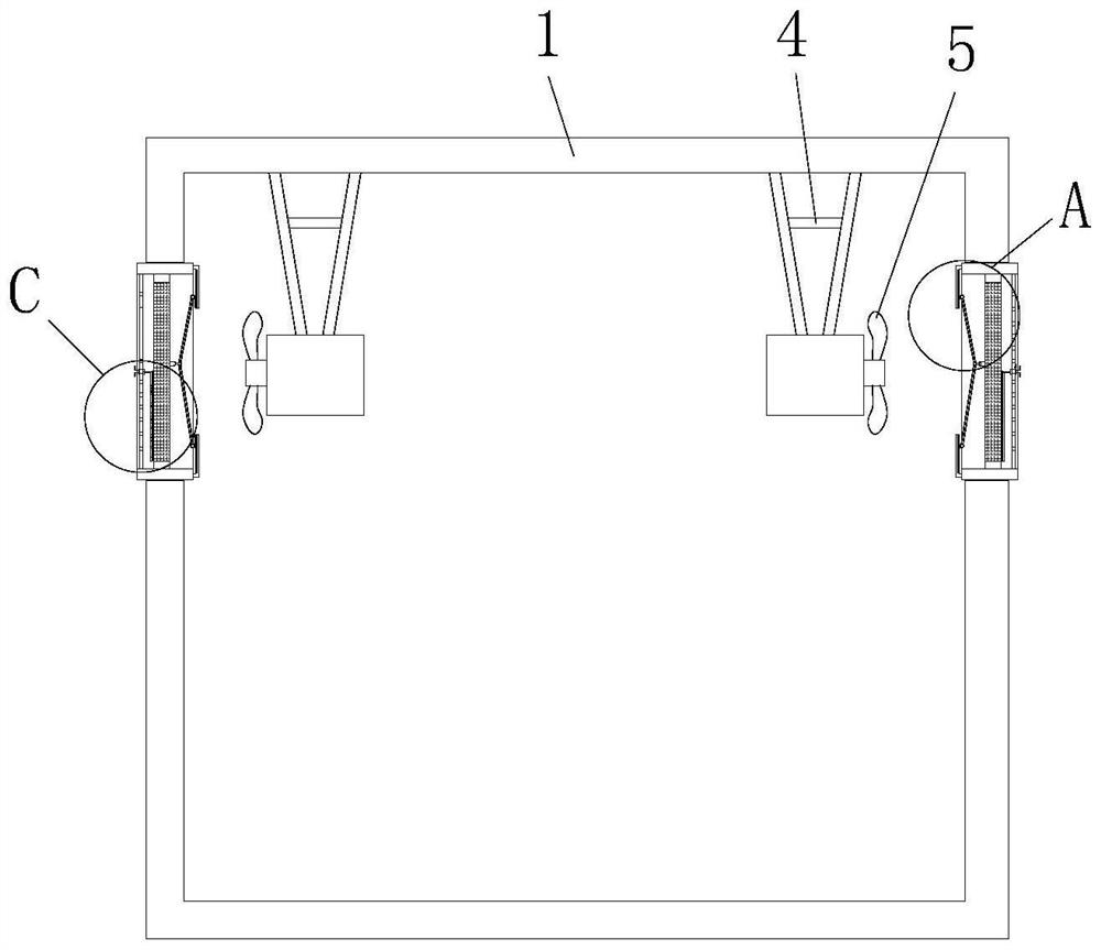
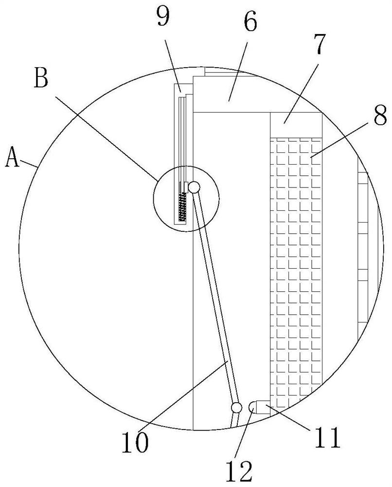
[0036] Example: An electrical seal protecting electrical components such as figure 1 - Figure 8As shown, it includes a sealed box 1, the sealed box 1 is a rectangular hollow structure, the outer wall of the sealed box 1 is movably installed with a box door 2, the box door 2 and the sealed box 1 are attached to each other, and the top of the sealed box 1 is fixed A protective top plate 3 is installed. The protective top plate 3 is a plate with an inverted V-shaped cross section. The outer wall of the protective top plate 3 is lined with rubber. The outer wall of the sealing box 1 is symmetrically provided with two cooling holes, and the cooling holes are circular through holes. The inner wall of the sealed box 1 is symmetrically provided with two cooling fans 5, and the cooling fans 5 are fixedly installed on the top of the inner wall of the sealed box 1 through the mounting bracket 4. , the inside of the heat dissipation hole is fixedly installed with a fixed frame 6, the cr...


PUM


Abstract

The invention relates to the technical field of electrical elements, and discloses an electrical sealing device for protecting electrical elements, which comprises a sealing box body, and the outer wall of the sealing box body is movably provided with a box door. According to the heat dissipation device, when the heat dissipation fan runs, air and heat are blown out through heat dissipation holes in the two sides, a folding plate movably installed in a fixing frame is subjected to the outward wind action, the folding plate rotates in the outer side direction and is folded, a first spring is compressed at the moment, and when the wind force constantly changes, the wind force action borne by the folding plate constantly changes, so that the heat dissipation effect is achieved. A folding plate is continuously folded and rotated in the fixed frame under the action of wind power and the elastic force of a spring I, and when the folding plate is rotated and folded, acting force is applied to an impact block movably mounted in a sleeve; at the moment, the impact block drives the connecting block to slide and impact the surface of the dustproof net under the action of external force, so that dust and sundries adhered to the dustproof net fall off, and the problem that the heat dissipation effect is affected due to blockage of meshes of the dustproof net is solved.

Description

technical field [0001] The present invention relates to the technical field of electrical components, in particular to an electrical sealing device for protecting electrical components. Background technique [0002] Electronic components are the basic elements in electronic circuits, usually individual packages with two or more leads or metal contacts. Electronic components must be connected to each other to form an electronic circuit with a specific function, such as: amplifiers, radio receivers, oscillators, etc. One of the common ways to connect electronic components is to solder to a printed circuit board. Electronic components may be individual packages (resistors, capacitors, inductors, transistors, diodes, etc.), or groups of various complexities, such as integrated circuits (op amps, resistor exclusions, logic gates, etc.), for To maintain the stability of the operation of electronic components, they are usually encapsulated with synthetic resin to improve insulatio...

Claims


Application Information

Patent Timeline
Patent Type & Authority Applications(China)
IPC IPC(8): H05K7/18H05K7/14H05K7/20H05K5/02H05K5/03H05K5/06B01D46/10B01D46/681B08B1/00B08B1/04
CPCH05K7/18H05K7/1401H05K7/20181H05K7/20145B08B1/002B08B1/04H05K5/0213H05K5/03H05K5/06B01D46/10
Inventor 孙浩波
Owner JIANGSU PROVINCE XUZHOU TECHNICIAN INST
Why Eureka
Try Eureka